TSC Alpha-4L Series Service Manual Download Page 31


30 

4. 

TROUBLESHOOTING


4.1   Common Problems 


The following guide lists the most common problems that may be encountered when 
operating this bar code printer. If the printer still does not function after all suggested 
solutions have been invoked, please contact the Customer Service Department of your 
purchased reseller or distributor for assistance. 
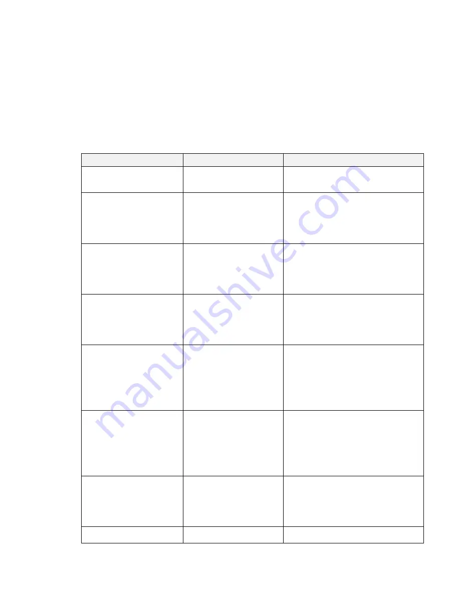
 

Problem 

Possible Cause 

Recovery Procedure 

Power indicator does not 

illuminate 

* The battery is not properly 

installed. 

* The battery is dead. 

* Reinstall the battery.   
* Switch the printer on. 
* Charge the battery. 

- The printer status from 

DiagTool shows “

Head 

Open

”. 

* The printer carriage is open.  * Please close the print carriage. 

- The printer status from 

DiagTool shows “

Out of 

Paper

”.. 

* Running out of media roll. 
* The media is installed 

incorrectly. 

* Black mark sensor is not 

calibrated.


* Supply a new media roll. 
* Please refer to the steps on section 3.4 to 

reinstall the media roll. 

* Calibrate the black mark sensor.


- The printer status from 

DiagTool shows “

Paper Jam

”. 

* Black mark sensor is not set 

properly. 

* Make sure media size is set 

properly. 

* Media may be stuck inside 

the printer mechanism. 

* Calibrate the black mark sensor. 
* Set media size correctly. 
 

Memory full 

( FLASH / DRAM )


* The space of FLASH/DRAM 

is full. 

* Delete unused files in the FLASH/DRAM. 
* The max. numbers of DRAM is 256 files.   
* The max. user addressable memory space 

of DRAM is 256KB. 

* The max. numbers of file of FLASH is 256 

files. 

* The max. user addressable memory space 

of FLASH is 2560KB. 

Poor Print Quality 

* Media is loaded incorrectly 
* Dust or adhesive 

accumulation on the print 
head. 

* Print density is not set 

properly. 

* Printhead element is 

damaged. 

* Reload the supply. 
* Clean the print head. 
* Clean the platen roller. 
* Adjust the print density and print speed. 
* Run printer self-test and check the print 

head test pattern if there is dot missing in 
the pattern. 

* Change proper media roll. 

Missing printing on the left or 

right side of label 

* Wrong label size setup. 

* Set the correct label size. 

Gray line on the blank label 

* The print head is dirty. 
* The platen roller is dirty. 

* Clean the print head. 
* Clean the platen roller. 

Summary of Contents for Alpha-4L Series

Page 1: ...i SERVICE MANUAL Alpha 4L Direct Thermal Portable Printer ...

Page 2: ...e Bluetooth Module 19 3 6 Replacing the Main Board Assembly 20 3 7 Replacing the Stepping Motor 21 3 8 Replacing the Gap Sensor Assembly 22 3 9 Replacing the Media Holder Assembly 23 3 10Replacing the Hand Open Sensor Assemble 24 3 11Replacing the Peel off Module 25 3 12Replacing the Black Mark Sensor Assembly 26 3 13Replacing the Charger Board Assembly 27 3 14Replacing the Wi Fi Module Option 28 ...

Page 3: ...el 7 Print head 8 Transmissive sensor Gap sensor 9 Media holder lock switch 10 Media holder 11 Media cover 12 Reflective sensor Black mark sensor 13 Platen roller 14 Tear Peeler bar Without for linerless model 15 Peeler module Note The media sensor position is selectable by factory adjustment Please refer to this figure for default settings Default center position black mark in back side 9 2 1 3 4...

Page 4: ...D card spec SD card capacity Approved SD card manufacturer V1 0 V1 1 MicroSD 128 MB Transcend Panasonic V1 0 V1 1 MicroSD 256 MB Transcend Panasonic V1 0 V1 1 MicroSD 512 MB Transcend Panasonic V1 0 V1 1 MicroSD 1 GB Transcend Panasonic V2 0 SDHC CLASS 6 MicroSD 4 GB Transcend The DOS FAT file system is supported for the SD card Folders files stored in the SD card should be in the 8 3 filename for...

Page 5: ...4 2 ELECTRONICS 2 1Summary of Board Connectors Main board top Connector Description J101 DC Jack 12V DC IN J101 J401 J404 CON101 CON102 CON103 ...

Page 6: ...ND 7 SD_Data0 8 SD_Data1 9 GND 10 GND J404 Micro USB Pin Description 1 NC 2 VBUS 3 TX 4 D 5 RX 6 D 7 RTS 8 GND 9 CTS 10 GND CON101 CON102 CON103 Battery CON101 pin1 4 CON102 pin1 for battery positive CON103 pin1 4 CON102 pin4 for battery negative CON102 pin2 3 for NTC Pin 1 Pin 1 Pin 10 Pin 8 ...

Page 7: ...cription J600 For LCD LED board Pin Description 1 3 3V 2 PEEL_E 3 PEEL_R 4 8V battery 5 LED_Charging off low battery 6 LED_Charging 7 Power KEY 8 Feed KEY 9 GND J600 J601 J602 J603 S1 J402 J702 J701 J501 J403 J703 S101 J301 BAT1 Pin 1 ...

Page 8: ...6 5 NC 6 V0 7 V1 8 V2 9 V3 10 V4 11 NC 12 NC 13 CAP2 14 CAP2 15 CAP1 16 CAP1 17 CAP3 18 NC 19 VOUT 20 GND 21 3 3V 22 LCM_D7 23 LCM_D6 24 LCM_D5 25 LCM_D4 26 LCM_D3 27 LCM_D2 28 LCM_D1 29 LCM_D0 30 LCM_RD 31 LCM_WR 32 LCM_A0 33 LCM_RST 34 LCM_CS Pin 1 ...

Page 9: ... LED_HALF BATTERY 6 LED_BT 7 LED_WIFI J603 For LCD board Pin Description 1 A 2 K 3 GND 4 3 3V 5 LED_ERROR 6 MANUAL KEY 7 INFO KEY S1 Download port Pin Description 1 3 3V 2 GND 3 RESET 4 BMS 5 CS 6 MISO 7 MOSI 8 CLK J402 WiFi connector Pin Description 1 3 3V 2 WIFI_RST 3 WIFI_RXD 4 WIFI_RST ...

Page 10: ...iption 1 3 3V 2 BT_RST 3 BT_RXD 4 BT_RTS 5 BT_TXD 6 BT_CTS 7 BT_DISCON 8 BT_CON 9 NC 10 GND J501 Stepping motor Pin Description 1 AOUT1 2 AOUT2 3 BOUT1 4 BOUT2 J701 Black mark sensor Pin Description 1 3 3V 2 BM_E 3 BM_R J702 Gap sensor Pin Description 1 3 3V 2 GAP_R ...

Page 11: ...D 2 GND J301 Print head Pin Description 1 VH 2 VH 3 VH 4 NC 5 LAT 6 TPH_CLK 7 3 3V_TPH 8 STB1 9 STB2 10 STB3 11 TM 12 GND 13 GND 14 GND 15 GND 16 GND 17 GND 18 GND 19 GND 20 GND 21 STB4 22 STB5 23 STB6 24 STB7 25 DI 26 VH 27 VH 28 VH 29 GND 30 GND ...

Page 12: ...11 S101 Charger station Pin Description 1 12V_IN 2 12V_IN 3 GND 4 GND BAT1 RTC battery Pin Description 1 GND 2 3V ...

Page 13: ...12 3 MECHANISM 3 1 Replacing the Platen Roller 1 Open the printer cover Use a tool to take the platen roller off Replace the platen roller 2 Reassemble the parts in the reverse procedures ...

Page 14: ...13 3 2 Replacing the Print Head Assembly 1 Use hex wrench 2 5 to remove two screws on lower cover 2 Open the printer cover Remove four screws on lower inner cover 3 Remove the upper cover carefully 1 2 ...

Page 15: ...14 4 Remove 2 screws on the each side of lower inner cover to remove the print head spring fixture 3 ...

Page 16: ...15 5 Loosen the connector lock black then disconnect the flat cable from the main board Remove the print head assembly 6 Replace the print head assembly 1 2 ...

Page 17: ...16 7 Reassemble the parts in the reverse procedures Print head ass y Print head spring fixture ...

Page 18: ...se loosen the connector lock brown then disconnect the cable Keys control board cable LCD control board cable 2 Remove 4 screws on the keys control board LCD control board and disconnect the peel off sensor connector by loosen the connector lock brown Keys control board LCD control board 3 Replace the keys control board LCD control board assembly 4 Reassemble the parts in the reverse procedures ...

Page 19: ...ule 1 Refer to section 3 2 to remove the upper cover 2 Disconnect the peel off sensor connector by loosen the connector lock for panel board Remove 1 screw 3 Replace the peel off sensor module 4 Reassemble the parts in the reverse procedures ...

Page 20: ...to remove the upper cover 2 Remove 2 screws on the Bluetooth control board Use a tool to remove the spacer support on the Bluetooth control board 3 Disconnect the connector on the board Replace the Bluetooth module 4 Reassemble the parts in the reverse procedures ...

Page 21: ...mbly 1 Refer to section 3 5 to remove the upper cover and Bluetooth control board 2 Remove 2 screws on the main board Disconnect all the connectors on the main board Replace the main board 3 Reassemble the parts in the reverse procedures ...

Page 22: ...1 Refer to section 3 2 to remove the upper cover 2 Remove 5 screws Disconnect the connectors on main board to take out the internal mechanism 3 Remove 2 screws to replace the stepping motor 4 Reassemble the parts in the reverse procedures ...

Page 23: ...Gap Sensor Assembly 1 Refer to section 3 7 to take out the internal mechanism 2 Loosen 2 springs 3 Remove 4 screws on the internal mechanism 4 Replace the gap sensor assembly 5 Reassemble the parts in the reverse procedures ...

Page 24: ...23 3 9 Replacing the Media Holder Assembly 1 Refer to section 3 8 to remove the gap sensor assembly 2 Replace the media holder assembly 3 Reassemble the parts in the reverse procedures ...

Page 25: ...10 Replacing the Hand Open Sensor Assemble 1 Refer to section 3 7 to take out the internal mechanism 2 Remove 1 screw to replace the hand open sensor assembly 3 Reassemble the parts in the reverse procedures ...

Page 26: ... and 3 7 to remove the platen roller and take out the internal mechanism 2 Remove the black mark sensor cover 3 Remove 4 screws on upper cover to take out the black mark sensor module 4 Replacing the Peel off cover 5 Reassemble the parts in the reverse procedures ...

Page 27: ...lacing the Black Mark Sensor Assembly 1 Refer to sections 3 11 to take out the black mark sensor assembly Disconnect the black mark sensor connector from main board 2 Reassemble the parts in the reverse procedures ...

Page 28: ...er Board Assembly 1 Refer to the section 3 7 to take out the internal mechanism 2 Disconnect the connector on the main board Remove 2 screws to replacing the charger board assembly 3 Reassemble the parts in the reverse procedures ...

Page 29: ... Fi module 4 Replace the Wi Fi module board 5 Arrange cable of antenna as indicated 6 Reassemble the parts in the reverse procedures Note If you replace the main board please check the Wi Fi signal band on configuration page for your using region If any questions please contact the Customer Service Department of your purchased reseller or distributor for assistance US EUR Antenna connector ...

Page 30: ... 15 Replacing the RTC Battery Option 1 Refer to section 3 14 to remove the WiFi module 2 Disconnect the connector on the main board 3 Replace the RTC battery 4 Reassemble the parts in the reverse procedures ...

Page 31: ...The printer status from DiagTool shows Paper Jam Black mark sensor is not set properly Make sure media size is set properly Media may be stuck inside the printer mechanism Calibrate the black mark sensor Set media size correctly Memory full FLASH DRAM The space of FLASH DRAM is full Delete unused files in the FLASH DRAM The max numbers of DRAM is 256 files The max user addressable memory space of ...

Page 32: ...31 Irregular printing The printer is in Hex Dump mode The RS 232 setting is incorrect Turn off and on the printer to skip the dump mode Re set the Rs 232 setting ...

Page 33: ... a new label roll Platen Roller 1 Turn the power off 2 Rotate the platen roller and wipe it thoroughly with 100 ethanol and a cotton swab or lint free cloth Clean the platen roller when changing a new label roll Tear Bar Peel Bar Use the lint free cloth with 100 ethanol to wipe it As needed Sensor Compressed air or vacuum Monthly Exterior Wipe it with water dampened cloth As needed Interior Brush ...

Page 34: ...33 Revise History Date Content Editor 2016 4 6 Modify section 3 14 Replacing the Wi Fi Module Camille ...

Page 35: ...1st Rd Wujie Township New Taipei City 23141 Taiwan R O C Yilan County 26841 Taiwan R O C TEL 886 2 2218 6789 TEL 886 3 990 6677 FAX 886 2 2218 5678 FAX 886 3 990 5577 Web site www tscprinters com E mail printer_sales tscprinters com tech_support tscprinters com TSC Auto ID Technology Co Ltd ...

Reviews: