background image

© Trynex International 2010  

(REV000) 


1 — 1

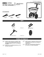
Owner / Operator’s Manual

FOR MODELS

SP-8550

LEADERS IN ICE CONTROL

This Manual Must Be Read Before Operating The Equipment

CUSTOMER COPY

Warren, Michigan 48089

800-725-8377

Protected by the following patents, #6,089,478, #6,088,865, #Des.425,915 

and other pending U.S. and foreign patent applications.

See Back 

Page for 

Details!

Warm Up

 to

with a

Winter Band!

F R E E

F R E E

Summary of Contents for SnowEx SP-8550

Page 1: ...ROL This Manual Must Be Read Before Operating The Equipment CUSTOMER COPY Warren Michigan 48089 800 725 8377 Protected by the following patents 6 089 478 6 088 865 Des 425 915 and other pending U S and foreign patent applications See Back Page for Details Warm Up to with a Winter Band F R E E F R E E ...

Page 2: ...ww snowexproducts com 1 2 Table of Contents Introduction 3 General Information and Registration 4 Safety Information 5 7 Spreader Assembly and Exploded Views 10 17 Wiring Instructions 18 Electrical System Information 19 22 Spreader Mounting System 23 24 Spreader Operating Information 26 28 Troubleshooting Information 29 31 Spreader Maintenance 32 Determine Vehicle Payload Chart 33 Warranty 34 Blan...

Page 3: ...U The Society of Automotive Engineers has adopted this SAFETY ALERT SYMBOL to pinpoint characteristics that if NOT carefully followed can create a safety hazard When you see this symbol in this manual or on the the machine itself BE ALERT Your personal safety and the safety of others is involved Defined below are the SAFETY ALERT messages and how they will appear in this manual RED Information tha...

Page 4: ...The benefits you are about to recognize are that of time money and effort We welcome you to the world of Trynex Performance Registration Record the following information in this manual for quick reference Spreader Model Number _____________________________________________________________________________________ Spreader Serial Number_______________________________ Controller Serial Number ________...

Page 5: ...er allow children to operate or climb on equipment Always check areas to be spread to be sure no hazardous conditions or substances are in the area Always inspect unit for defects broken worn or bent parts weakened areas on spreader or mount Always shut off vehicle and power source before attempting to attach or detach or service spreader unit Be sure vehicle power source is properly braked or cho...

Page 6: ...ccidents are preventable and caused by human error Exercising of care and precautions must be observed to prevent the possibility of injury to operator or others Never operate equipment when under the influence of alcohol drugs or medication that might alter your judgment and or reaction time Before working with the spreader secure all loose fitting clothing and unrestrained hair Always wear safet...

Page 7: ... Trynex International 2010 1 7 Safety and Warning Labels D 6546 D 6548 D 6335 D 6544 D 6545 D 6859 Model SP 8550 SERIAL NUMBER ON REVERSE SIDE ...

Page 8: ... Trynex International 2010 1 8 THIS PAGE INTENTIONALLY LEFT BLANK ...

Page 9: ... Trynex International 2010 1 9 THIS PAGE INTENTIONALLY LEFT BLANK ...

Page 10: ... Trynex International 2010 1 10 Auger Drive Assembly Parts Breakdown Model SP 8550 ...

Page 11: ... h c t i P e l b a i r a V 6 1 8 6 D 1 r o t o M t u p t u O h g i H t l o V 2 1 5 2 8 6 D 1 n o i s s i m s n a r T r e g u A 1 r e v o C r o t o M r e g u A 8 6 8 6 D 2 With Locking Hex Bolt r e l p u o C e v i r D r e g u A s n a r T 2 4 8 6 D 1 r e d y p S e n a h t e r U 3 4 8 6 D 2 g n i r a e B r e g u A 5 4 8 6 D 3 k c o t S y e K 6 1 3 3 7 8 6 D 4 1 2 13 Serrated Flange Nut 5535 D 7 H W H...

Page 12: ... Trynex International 2010 1 12 Spinner Drive Assembly Parts Breakdown Model SP 8550 ...

Page 13: ...t Washer Spinner Shroud 5 16 18 Nylox Zinc Plastic Handle Hair Pin Clip Drive Pin Spinner Motor Cover Long Rivet Drive Motor Left Hand Latch 8550 Spinner Drive Enclosure Right Hand Latch Shoulder Bolt 5 16 18 x 1 3 4 Hex Head Bolt Plastic Deflector 1 4 20 Nylox Stainless 3 8 16 x 1Serrated Flange Bolt 1 4 20 x 3 4 Serrated Flange Stainless 5 16 18 x 1 1 8 5 16 Flat Washer Plastic Deflector Spinner...

Page 14: ... Trynex International 2010 1 14 Hopper Assembly Parts Breakdown Model SP 8550 ...

Page 15: ...N k c o l y N 6 1 5 8 3 1 6 D 2 e t a l P t l o B 5 1 8 6 D 1 r o t a r b i V y t u D y v a e H 5 1 5 6 D 1 r e p p o H x x a M V 0 0 8 6 D 1 y l b m e s s A V d e t r e v n I 8 0 8 6 D 1 e l f f a B e g r a h c s i D 7 0 8 6 D 4 s e t a l P g n i k c a B V d e t r e v n I 1 1 8 6 D 1 Front Top Screen 8 4 8 6 D 4 r e l l i r D f l e S H W H 5 1 x 4 1 4 7 8 6 D 1 9 4 8 6 D Rear Top Screen Flat Wash...

Page 16: ... Trynex International 2010 1 16 Frame Assembly Parts Breakdown Model SP 8550 ...

Page 17: ...4 D 2 4 t u N k c o l y N 8 3 4 2 1 4 D 6 1 t l o B x e H d e t a r r e S 1 x 3 1 2 1 8 2 5 6 D 1 t e k c a r B p o t S t h g i R 6 3 5 6 D 1 t e k c a r B p o t S t f e L 7 3 5 6 D 2 t n e m d l e W e m a r F e d i S 1 0 8 6 D 1 l i a R t n o r F r e w o L r e p p U 4 0 8 6 D 1 n o r p A r a e R 5 0 8 6 D t r o p p u S s n a r T r o t o M r e g u A 5350 D ...

Page 18: ...or use existing access hole for the control portion of the harness and route connector and harness through hole Be sure to check the area on the other side of the fire wall to make sure you are not drilling into the vehicle harness or a control module Generally you can drill on either side of the steering wheel for a good location Step 4A The power harness from control box to battery will need to ...

Page 19: ...over 2 9 D6354 Vibrator Switch 3 Terminal Red 1 10 D6784 Utility Work Light 1 11 D6785 Light Kit Spreader Harness 1 12 D6786 Light Kit Vehicle Harness 1 IMPORTANT In the off season remove control and put in a cool dry place The interior summer temperatures could damage circuit board and void warranty 10 6 1 12 3 8 4 2 5 9 will void warranty Special Notes 1 All external connections must have dielec...

Page 20: ...onnect to control mating half Positive White with Red Tracer to battery Ring Terminal Negative Black to battery Ring Terminal NOTE A Leads must only be attached to battery B 100 Amp breaker must be inserted D6837 Control Power Cable with D6840 Breaker Key Part No Description Qty D 6837 Control Power Cable 1 D 6839 6 GA Breaker Wire 1 D 6840 100 AMP Resetable Breaker 1 Model SP 8550 and put in a co...

Page 21: ...Model SP 8550 AUGER Black Negative MAIN POWER PLUG SPREADER AUGER Red Positive SPINNER Blue Positive SPINNER Orange Negative VIBRATOR Green Negative VIBRATOR Yellow Positive Yellow Positive Green Negative VIBRATOR POWER PLUG SPINNER POWER PLUG Orange Negative Blue Positive ...

Page 22: ...e Positive AUGER Red Positive AUGER Black Negative Red Positive Black Negative Anderson Block 2 Pos Anderson Block 4 Pos VIBRATOR OUTPUT Yellow Positive VIBRATOR OUTPUT Green Negative SPINNER OUTPUT Blue Positive SPINNER OUTPUT Orange Negative BUMPER PLUG CONTROL OUTPUT PLUG SPINNER VIBRATOR CIRCUIT AUGER CIRCUIT OUTPUT NOTE Reference Bumper Plug for Color Code ...

Page 23: ...ss to vehicle electrical system Once wire taps are installed check to make sure stop lamp works when brake pedal is pressed Properly Model SP 8550 complete installation by tying up any loose wires with ty wraps also add electrical tape over both connections to insure a solid electrical connection Some newer trucks have auxiliary stop lamp power leads already at the rear for these types of applicat...

Page 24: ...raps Figure 1 Cross Left Upper to Right Lower Cross Right Upper to Left Lower y t Q n o i t p i r c s e D o N t r a P y e K D 4116 1 2 13 x 1 1 2 Hex Bolt 4 D 4119 1 2 Flat Washer 4 4 t u N k c o L 2 1 0 2 1 4 D D 4121 3 8 16 x 1 Hex Bolt 4 4 t u N k c o L 8 3 4 2 1 4 D 4 p a r t S t e h c t a R 856 6 D D 6536 Adj Stop Bracket RT 1 D 6537 Adj Stop Bracket LT 1 1 p r a T 5 5 8 6 D 1 Bungie Straps 1...

Page 25: ...milar marking device mark hole locations Step 6 Before drilling holes look beneath the approximate area where each hole will be located Make sure there are no vehicle components that will be in the path of the drill before doing this step If there are interferences you can relocate holes as needed making sure there are at least two forward and two rearward of the front to back centerline Step 7 In...

Page 26: ... Trynex International 2010 1 25 THIS PAGE INTENTIONALLY LEFT BLANK ...

Page 27: ...ng to remove material baffle The main baffle assembly D 6808 MUST never be removed from its original factory installed position unless the unit is being serviced or the Optimum Flow Kit is being installed BAFFLE EXTENSION INSTRUCTIONS The Baffle Extension is installed at the time of assembly The main purpose of this baffle is to keep dry free flowing material from leaking out If you plan on using ...

Page 28: ...sand mix a 1 1 ratio for Sand Salt mix is recommended to prevent the material from freezing SPREADING TIPS Never exceed 10 m p h when spreading For a wider pass increase spinner speed For a heavier pass drive slower or increase auger speed Never operate spreader near pedestrians Spread ice melters with the storm to prevent unmanageable levels of ice Calculate spread pattern when near vegetation 85...

Page 29: ... poor connection elsewhere in the system If there are any problems while operating the spreader refer to Troubleshooting Guide AUTO REVERSE AR FUNCTION If your controller displays OL this could indicate a jammed auger To engage the Auto Reverse AR function Step 1 Shut the Main Power Switch OFF for 3 seconds Step 2 Turn the Main Power Switch ON When the machine starts back up the AR sequence will a...

Page 30: ...inary Checks Be sure all electrical connections are tight and clean Be sure nothing is jammed in the hopper Motor doesn t run Controller shut down Material not owing from hopper Audible alarm beeping and display shows OL or OH Audible alarm beeping display shows E1 Audible alarm beeping display shows EO Audible alarm beeping display shows LB Check all connections Replace fuse Replace motor Careful...

Page 31: ...BY HAND SHOULD TURN FREELY REPLACE ALL CORRODED CONNECTIONS PLUG IN SPREADER OPEN ACCESS COVER AND PLUG TOGETHER REPLACE HARNESS REPLACE ALL CORRODED CONNECTIONS TIGHTEN OR REPLACE REPLACE DEFINITION AMP DRAW TOO HIGH DEFINITION OPEN CIRCUIT BETWEEN MOTOR AND CONTROLLER BAD ELECTRICAL CONNECTION LOW BATTERY LESS THAN 12 VOLT OUTPUT DEAD SHORT IN MOTOR CIRCUIT BAD CONTROLLER CHECK WITH TEST KIT CON...

Page 32: ...S MATERIAL DOES NOT FLOW MATERIAL ISSUE AUGER RUNS PROPER DIRECTION AUGER RUNS BACKWARDS REPLACE VEHICLE HARNESS CHECK CONNECTIONS AT AUGER MOTOR FOR REVERSE POLARITY POLARITY CORRECT REPLACE SPREADER HARNESS MATERIAL OBSTRUCTION REMOVE OBSTRUCTION AUGER RUNS BACKWARDS RUN 12 VOLT TO AUGER CIRCUIT ON SPREADER POWER CORD TURN ON VIBRATOR SLOW MATERIAL FLOW TURN ON VIBRATOR INCREASE AUGER SPEED MATE...

Page 33: ...nning and end of the season and each time plugs are disconnected Gently wash unit after each use to prevent material build up and corrosion CAUTION When pressure washing motor enclosure area stay at least 36 away from all electrical items Paint or oil all bare metal surfaces at the end of the season Apply small amount of light oil to latches as needed If motor cover is removed for any reason use s...

Page 34: ...eners refer to the Torque Chart below for the recommended fastener torque values These torque values apply to mount assembly fasteners except those noted in the instruction Recommended Fastener Torque Chart ft lb 1 4 20 5 16 18 3 8 16 3 8 24 7 16 14 1 2 13 9 16 12 5 8 11 3 4 10 7 8 9 1 8 SIZE SAE Grade 8 6 11 19 24 30 45 66 93 150 202 300 9 18 31 46 50 75 110 150 250 378 583 13 28 46 68 75 115 165...

Page 35: ... to the dealer from where the product was purchased unless otherwise authorized by Trynex Trynex reserves the right to determine if any part is defective and to repair or replace such parts as it elects This warranty does not cover shipping costs of defective parts to or from the dealer LIMITATION OF LIABILITY Neither Trynex nor any company affiliated with it makes any warranties representations f...

Page 36: ...ynex Dealer sold you the correct product for your needs application Yes No 10 How would you rate your overall satisfaction with your SnowEx Dealer 11 How would you rate your overall satisfaction with your SnowEx Product 12 Would you purchase another Trynex Product 13 IfyouwouldliketoreceiveE MailALERTSfornewproducts bulletinsorspecialpromotionspleasesupplyaddress __________________________________...

Page 37: ...RK DR WARREN MI 48089 2667 From Postage Required Post Office will not deliver without proper postage Simply Fill Out Your Warranty Registration and Return It to the Factory Warm Up to with a Winter Band F R E E F R E E ...

Reviews: