2. TRP-C07 Hardware description
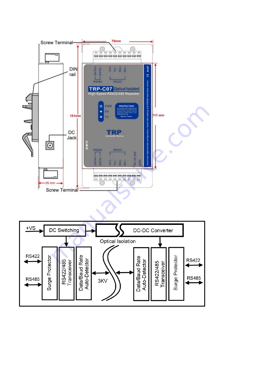
2-1. Panel Layout
2-2. TRP-C07 block diagram
2-3. LED indicators PWR LED
: System is ready.
RX LED:
RS-422/485 receiving.
TX LED:
RS-422/485 transmitting.
Page 1: ...ange without prior notice in order to improve reliability design and function and dosed not represent a commitment on the part of the manufacturer No part of this manual may be reproduced copied or tr...
Page 2: ...nput range DC power supply Automatic data format configuration Auto direction flow control on RS 485 Auto baud rate switching from 300bps to 115 2Kbps RS 485 bi directionally communication 3000 DC iso...
Page 3: ...2 TRP C07 Hardware description 2 1 Panel Layout 2 2 TRP C07 block diagram 2 3 LED indicators PWR LED System is ready RX LED RS 422 485 receiving TX LED RS 422 485 transmitting...
Page 4: ...and running It is highly recommended use the power jack specification 5 5 2 1 12mm if the power supply is from external DC plug Warning User can only choose one of following 2 power sources 1 Externa...
Page 5: ...Trycom web www trycom com tw The testing utility includes RS 422 test utility Test422 exe for DOS DEMO exe for Windows and RS 485 utility Test485 exe for DOS TRPCOM for Windows 4 1 RS 422 Loop Back Te...
Page 6: ...utput status 4 2 RS485 test The wiring connection is as below Step1 Install TRPCOM utility TRPCOM is a test utility which may help user to test TRP C07 with RS485 device easily Double click Setup exe...
Page 7: ...Step3 Send command 01M and press Send Step4 Data response received Test complete...