TECHNICAL CHARACTERISTICS:
Voltage:
220 V~
Frequency:
60 Hz
Current:
10 A
Speed:
3 450 RPM
Motor Rated Power:
3 Hp
Maximum Motor Power:
4 Hp
Maximum Pressure:
116 PSI
Tank Capacity:
63.4 Gal
IP Grade:
IP20
Air Flow:
7,7 CFM - 40 PSI
5,7 CFM - 90 PSI
Power Cord Grips Type:
Y
All conductors are:
1,5 mm
2
x 3C with 221 ºF Insulating
Temperature
Build quality:
Basic insulation.
Insulation quality:
Class l
Thermal insulation of motor winding:
Class B
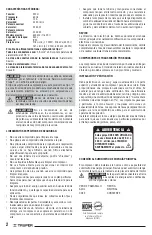
To avoid risk of electrical shock or serious accident,
if power cord gets damaged it shall be repaired by the manufacturer
or by Truper
®
Authorized Service Center
Power cord grips used in this product: Type”Y”.
Assembly design in this product causes insulation to be affected
by liquid spills or splashing.
Before gaining access to terminals, all
power circuits shall be disconnected.
We do not recommend using power
cord extensions with compressors. Using that type of
extension cause power drops resulting in motor potency
loss and overheating. Instead of using an extension cord
increase the compressor’s action scope connecting a
longer hose into the outlet. Connect additional hose
lengths as needed.
BELT DRIVE AIR COMPRESSORS.
- Do not use compressed air to clean clothes.
- Do not apply compressed air directly to skin.
- Do not apply compressed air for breathing purposes
unless the air is filtered with a filter specifically for built to
that purpose.
- Do not use open-air piping. It could lash out and
cause injuries.
- Do not use flammable liquids to clean the compressor.
- Do not use an open fire to inspect inside the compressor or
the pressure deposit.
- Wear eye protection when using compressed air to clean
the unit.
- Use caution not to blow particles towards people: always use
an air gun for cleaning.
- Double-check all the auxiliary fixtures are functioning
adequately and have the right capacity for the application.
- Inspect regularly that all covers are fixed and firmly set.
- Replace all parts, tools and accessories when unfit for a safe
operation.
- Install a check-valve or a cut valve in the inlet piping in case
compressor shall be parallel coupled with a second
compressor or if it will be connected to an air supply system.
- Double-check all piping and hoses connected to the
compressor have the right diameter, and, adequate
resistance for the maximum pressure delivered by the
compressor.
- Install the compressor making available an adequate
ventilation air supply towards the unit. Use care not to
restrict air ducts through the inlets in the cover and
motor fan.
INSPECT:
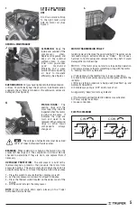
Inspect the pumps’ rotation direction during the initial start up.
Verify any modification in the electric components’ or connections.
Turn off the compressor and disconnect from the power outlet.
Ventilate completely before disassembling any component or
making any maintenance service.
BELT DRIVE AIR COMPRESSORS
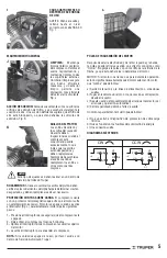
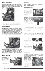
Belt drive air compressors are shipped with the wheels installed.
The model installed on wheels absorbs vibration but shall be set
on firm and leveled ground.
INSTALLATION AND VENTILATION
To service the compressor allow adequate access and free space
up and around the unit. It needs adequate protection against
weather. Good ventilation is essential. To gain maximum efficiency
admission air shall be as cold and clean as possible (a 37.4 ºF
drop in temperature will increase 1% the delivered air volume).
Gas impurities and particles, abrasive dust and corrosive gasses
are especially harmful. The exhaust vapors are hazardous if
compressed air is used to supply breathing devices.
Set the compressor as far away as possible from the work areas
to prevent from suctioning particles generated by the job (paint,
dust, etc.)
CONNECTION TO THE MAIN POWER SUPPLY
The compressor shall be set as close as possible to the main
power supply. Double-check the power supply matches the voltage
indicated in the motor nameplate.
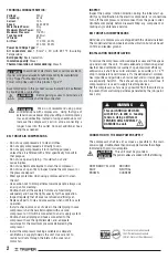
This unit must be grounded.
The power cables are coded with the following
colors:
GREEN AND YELLOW GROUND
BLUE NEUTRAL
BROWN CURRENT
3
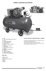
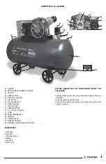
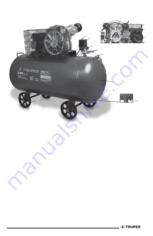
COMPRESSOR FULL DIAGRAM
A) HANDLE
B) MOTOR INTER-CONNECTION BOX
C) MOTOR
D) CHECK VALVE
E) BELT WITH GUARD
F) AIR FILTER
G) OIL FILLING CAP
H) PUMP CASING
I) OIL SPYHOLE
J) PRESSURESTAT
K) 1/4’’ OUTLET VALVES
L) TANK
M) TANK MANOMETER
N) WHEELS
O) PURGE VALVE
P) SWITCH BUTTON
Q) THERMAL OVERLOAD PROTECTOR
ACCESSORIES:
1 Oil Bottle
2 Air Filters
1 Oil Deposit Cap
4 Wheels
4 Rondanas
4 Cotter pins
BEFORE CONNECTING THE COMPRESSOR VERIFY THE
FOLLOWING:
Feeding voltage shall match voltage indicated in the compressor
nameplate.
Air gauge readings shall be zero.
Oil level in the compressor pump casing shall reach the mark in
the level indicator.
O
A
A
N
N
L
K
M
J
P
B
C
D
E
F G
H
I
Q
C
D


