


U N D E R B A R R E F R I G E R A T I O N
U N D E R B A R R E F R I G E R A T I O N
truemfg.com
TEC_TM_114 | REV. A | EN
04/26/2021
Page 14 of 28
TEC_TM_114 | REV. A | EN
04/26/2021
Page 15 of 28
truemfg.com
Cabinet Operation
Startup
• The compressor is ready to operate when the unit is purchased.
All you need to do is plug in the cooler.
• Excessive tampering with the control could lead to service
difficulties. If replacing the temperature control is ever needed,
be sure to order the replacement from your TRUE dealer or
recommended service agent.
• Good air flow inside your TRUE unit is critical. Take care to
prevent product from pressing against the sides or back
wall and coming within 4" (101.6 mm) of the evaporator
housing. Refrigerated air off the evaporator coil must circulate
throughout the cabinet for even product temperatures.
NOTE:
If the unit is disconnected or shut off, wait 5 minutes
before restarting.
RECOMMENDATION
– Before loading product, run your TRUE
unit empty for 24 hours to verify proper operation. Remember,
our factory warranty
DOES NOT
cover product loss!
Temperature Control & Light Switch Location
The switch is located on the front of the evaporator housing
toward the front of the cabinet.
The light symbol
shows the approximate location of the light
switch.
Light Switch on Glass Door Models
Inside left wall or top ceiling.
Mechanical Temperature Control or
Electronic Temperature Control Without Digital Display
Inside back corner.
Electronic Temperature Control without Digital Display
Behind front grill.
Mechanical Temperature Control or Electronic
Temperature Control without Digital Display
Inside right wall or back wall.
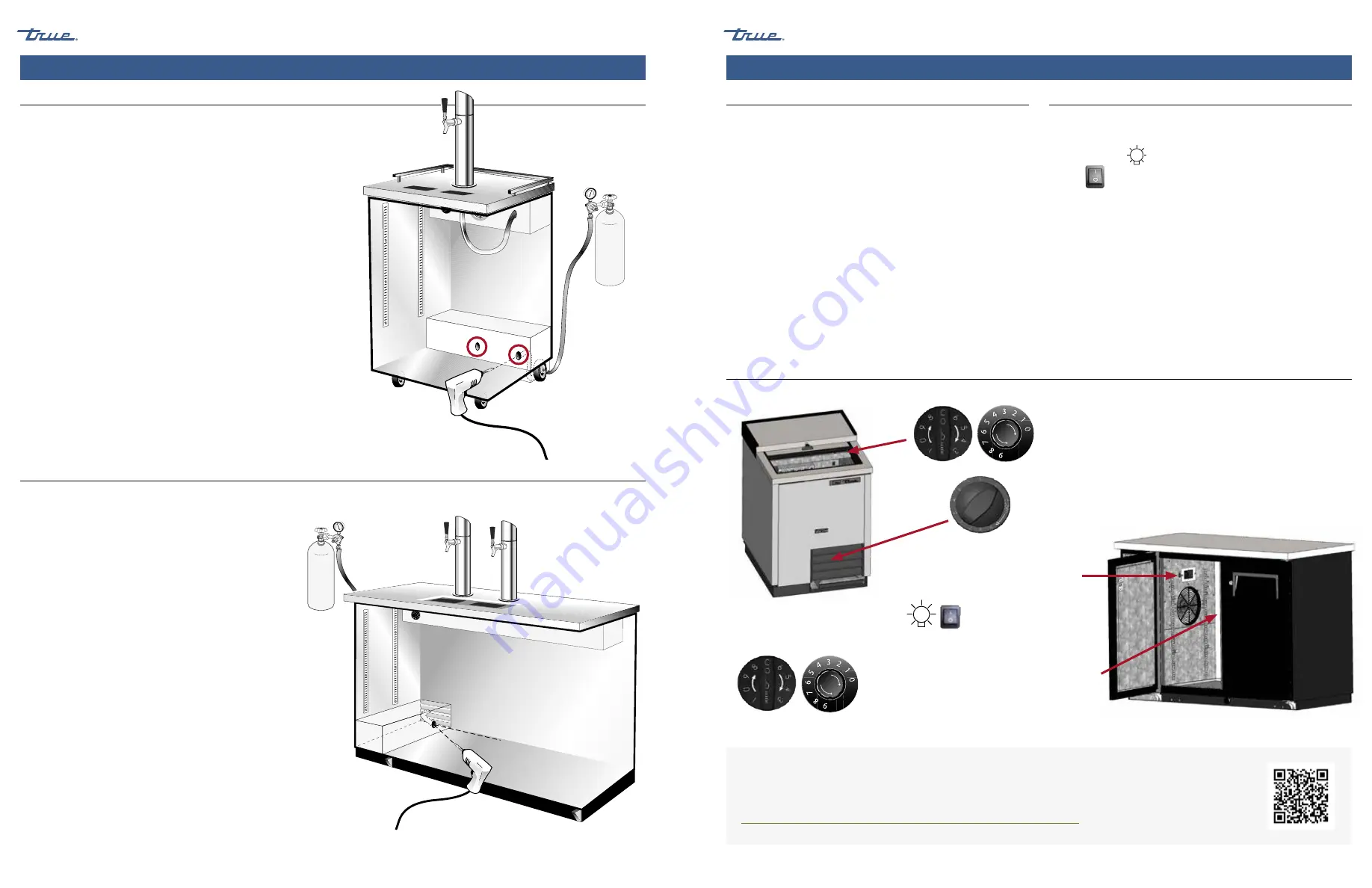
Cabinet Setup (cont.)
This instruction is TRUE’s recommended procedure for installing a
remote CO2 container.
Required Tools
• Pliers
• Silicone Sealer
• 1/2" Drill bit
• Drill
Procedure
1.
With pliers, remove the black knockout plug.
NOTE:
The knockout plug for CO2 lines can be located in
two different areas. See the diagram for locations.
2.
Drill a hole through the cabinet wall and into the compressor
compartment.
3.
Route the CO2 line through the knockout hole and exiting
behind the rear castor underneath the rear grill. See the
diagram.
4.
Apply silicone sealer to the hole around the CO2 line to prevent
cold air leakage.
This instruction is TRUE’s recommended procedure for installing a
remote CO2 container.
Required Tools
• Pliers
• Silicone Sealer
• 1/2" Drill bit
• Drill
Procedure
1.
With pliers, remove the black knockout plug.
2.
While holding the drill at a 30° angle, drill through the
insulation.
NOTE:
This hole should line up with a pre-punched hole in
the compressor compartment.
3.
Route the CO2 line through the knockout hole and through the
rear grill.
4.
Apply silicone sealer to the hole around the CO2 line to prevent
cold air leakage.
TDD-1 CO2 Knock-Out
TDD-2, -3, -4 (and Club Top Models) CO2 Knock-Out
OFF
9
8
7
6 5 4
3
2
Knockout plug can be located
at either location.
CO
LD
ER
CO
LD
ER
FOR MORE INFORMATION
For more information regarding a cabinet's temperature control adjustment or general sequence of operation,
please see our
Temperature Control Adjustment — Sequence of Operation Manual
in our resource library at
https://www.truemfg.com/Service-Manuals/Sequence-of-Operation
or follow the QR code.
Model(s) – TDB, TBB, TDD, TD, T-GC


