Summary of Contents for 47260
Page 59: ......
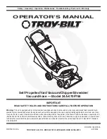
The Troy-Bilt 47260 is a powerful and versatile lawn mower designed to help you tackle your yard work with ease. Make sure you have the Owner/Operator Manual on hand for step-by-step instructions on how to operate and maintain your mower. Download the manual for free from manualshive.com.
Page 59: ......