


17
WARNING:
Before
inspecting, cleaning or servicing
the machine, shut off engine,
wait for all moving parts to come
to a complete stop, disconnect
spark plug wire and move wire
away from spark plug. Remove
ignition key on electric start
models.
Failure to follow these
instructions can result in serious
personal injury or property
damage.
NOTES
1 -
Check after first 2 hours of break-in operation.
2 -
Before each use.
3 -
Every 5 operating hours.
4 -
Every 10 operating hours.
5 -
Every 30 operating hours.
6 -
Change more frequently in dusty conditions.
7 -
See Engine Owner’s Manual for service
recommedations.
8 -
Whichever time interval occurs first.
9 -
Change after first 2 hours of break-in
MAINTENANCE SCHEDULE
PROCEDURE
NOTES
Check motor oil level
2, 3
Clean engine
2, 7
Check drive belt tension
1, 4
Check nuts and bolts
1, 4
Change motor oil
4, 6, 9
Lubricate tiller
4
Service engine air cleaner system
7
Check gear oil level in transmission 1, 5
Check tines for wear
5
Check air pressure in tires
(if unit has pneumatic tires)
5
Service spark plug
7
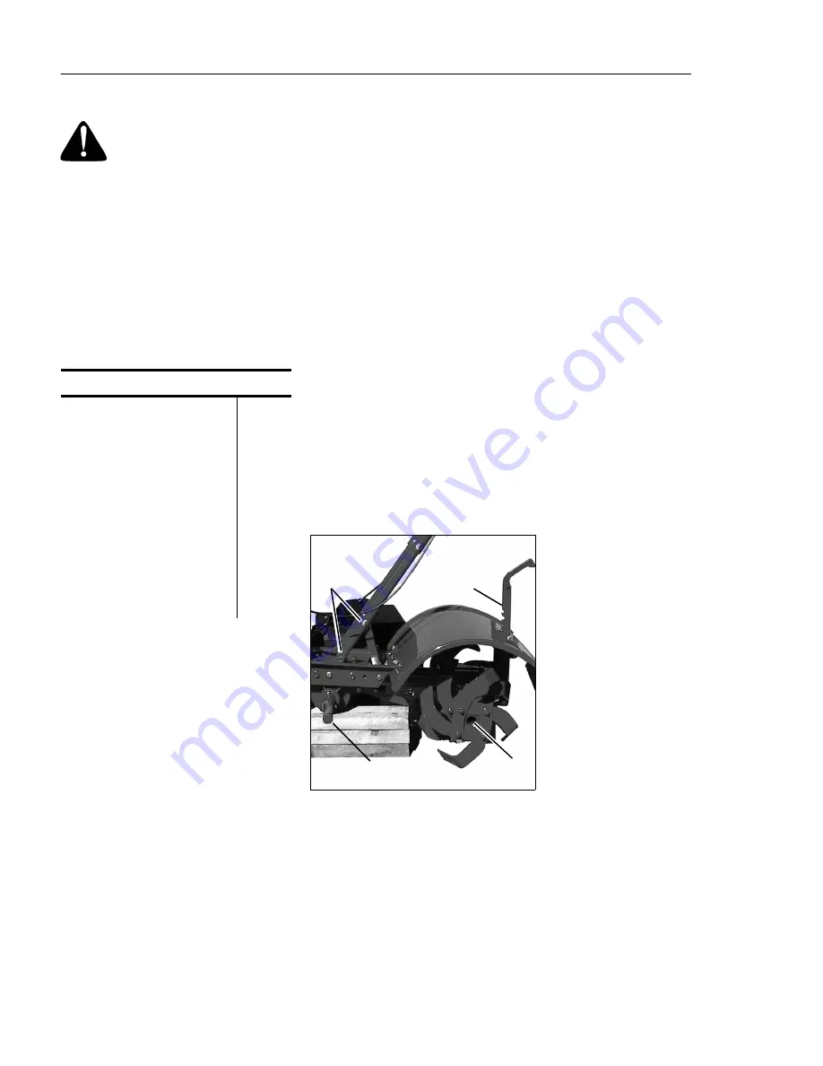
TILLER LUBRICATION
After every 10 operating hours, oil or
grease the lubrication points shown in
Figure 5-1 and described below.
Use clean lubricating oil (#30 weight motor
oil is suitable) and clean general purpose
grease (grease containing a metal lubricant
is preferred, if available).
• Remove the wheels, clean the wheel shaft
(A, Fig. 5-1) and apply a thin coating of
grease to the wheel shaft.
• Grease the back, front and sides of the
depth regulator lever (B, Fig. 5-1).
• Remove the tines and clean the tine shaft
(C, Fig. 5-1). Use a file or sandpaper to
gently remove any rust, burrs or rough
spots (especially around holes in shaft).
Apply grease to ends of shaft before install-
ing tines.
• Oil the threads on the handlebar height
adjustment screws and the handlebar
attaching screws (D, Fig. 5-1).
B
D
A
C
Figure 5-1
If a cover is leaking, check for loose
screws. If the screws are tight, a new
gasket or oil seal may be required.
If the leak is from around a shaft and oil
seal, the oil seal probably needs to be
replaced. See your authorized dealer or
contact the factory for service or advice.
IMPORTANT: Never operate the tiller if
the transmission is low on oil. Check
the oil level after every 30 hours of
operation and whenever there is any oil
leakage.
CHECK HARDWARE
Check for loose or missing hardware af-
ter every 10 operating hours and tighten
or replace (as needed) before reusing
tiller
Be sure to check the screws underneath
the tiller hood that secure the transmis-
sion cover and the Depth Regulator Lever
to the transmission.
CHECK TIRE PRESSURE
(Models with pneumatic tires)
Check the air pressure in both tires. The
air pressure should be between 15 PSI
and 20 PSI (pounds per square inch).
Keep both tires equally inflated to help
prevent machine from pulling to one
side.
TRANSMISSION
GEAR OIL SERVICE
Check the transmission gear oil level
after every 30 hours of operation or
whenever you notice any oil leak. Oper-
ating the tiller when the transmission is
low on oil can result in severe damage.
A. To Check the Transmission
Gear Oil Level:
1. Check the gear oil level when the
transmission is cool. Gear oil will
expand in warm operating temperatures
and this expansion will provide an incor-
rect oil level reading.
2. With the tiller on level ground, pull the
Depth Regulator Lever all the way up.
3. Remove the oil fill plug (A, Fig. 5-2)
from the transmission housing and look
inside the oil fill hole to locate the main
drive shaft situated below the hole.
CHECK FOR OIL LEAKS
Before each use, check the tiller for signs of
an oil leak — usually a dirty, oily accumu-
lation either on the unit or on the floor.
A little seepage around a cover or an oil
seal is usually not a cause for alarm. How-
ever, if the oil drips overnight, then imme-
diate attention is needed. Ignoring an oil
leak can result in severe transmission
damage!
SECTION 5: MAINTENANCE


