


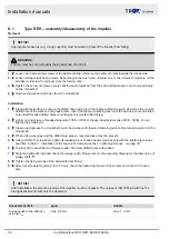


D.2
Type RZH - removal/assembly of the complete rotor set
WARNING!
Attention! The impeller and crankshaft must not be separated.
Removal of nominal size 400-1000
1.
De-energize the fan
2.
Remove the V-belt drive and belt protection box.
3.
Secure the rotor set against falling
4.
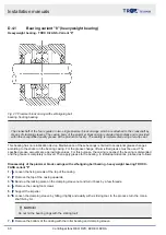
Disassembly of the bearing (
‘Heavyweight bearing - TROX X-FANS - Variant "8"’ on page 60
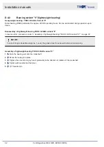
assembly of lightweight bearing TROX X-FANS variant "9"’ on page 62
)
5.
Disassembly of inlet cover grille on the actuator side
6.
Disassembly of the bearing block (support frame) on the actuator side
7.
Disassembly of bellmouth inlet on the actuator side
8.
Pull out the complete rotor set on the actuator side with suitable lifting tools
Installation of nominal size 400-1000
1.
Step 1 - 8 in reverse order; proceed as under
2.
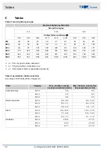
Align the bellmouth inlet (airway width "S" according to TROX X-FANS drawing)
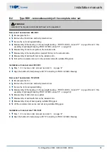
Removal of nominal size 1120-1600
1.
De-energize the fan
2.
Remove the V-belt drive and belt protection box.
3.
Secure the rotor set against falling
4.
Disassembly of the bearing (
‘Heavyweight bearing - TROX X-FANS - Variant "8"’ on page 60
assembly of lightweight bearing TROX X-FANS variant "9"’ on page 62
)
5.
Disassembly of both inlet cover grilles
6.
Disassembly of bellmouth inlet on the actuator side
7.
Disassembly of top of casing using suitable lifting gear
8.
Lift the complete rotor set up and out using suitable lifting gear
Installation of nominal size 1120-1600
1.
Step 1 - 8 in reverse order; proceed as under
2.
Align the bellmouth inlet (airway width "S" according to TROX X-FANS drawing)
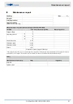
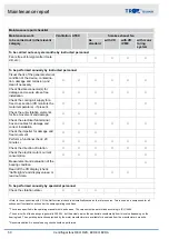
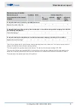
Installation manuals
Centrifugal fans REH; RZH; BVREH; BVRA
57


