


15
ASSEMBLY STEPS
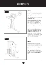
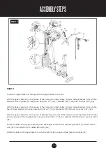
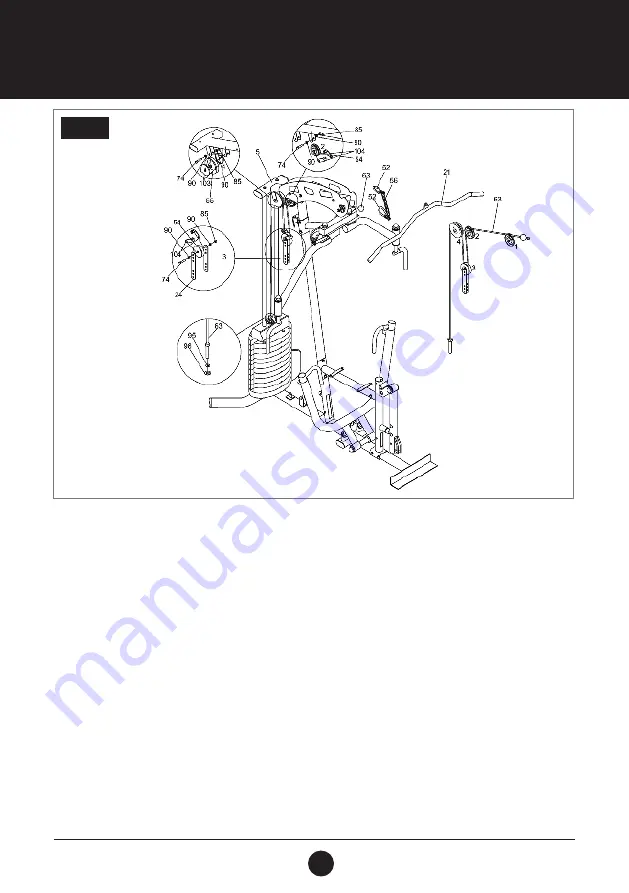
STEP 7:
Thread the Upper Cable (63) through all the Pulley Brackets of the unit
With the Upper Cable (63) in the groove of the Pulley (54), install Pulley (2) and 2 Pulley Brackets (104) into the
bracket of the Top Beam (5) using 1 Hex Bolt (3/8” x 2”) (74), 2 Washers (3/8”) (90) and 1 Locknut (3/8”) (85).
With the Upper Cable (63) in the groove of the Pulley (54), install Pulley (3) and 2 Pulley Brackets (104) into the
top of Pulley Bracket (24) using 1 Hex Bolt (3/8” x 2”) (74), 2 Washers (3/8”) (90) and 1 Locknut (3/8”) (85).
With the Upper Cable (63) in the groove of the Big Pulley (55), install the Pulley (4) and 2 Big Pulley Guards (103)
into the bracket of the Top Beam (5) using 1 Hex Bolt (3/8” x 2”) (74), 2 Washers (3/8”) (90) and 1 Locknut (3/8”)
(85).
Secure the Bolt End of Upper Cable (63) onto the Weight Selection Rod (29) using 1 Washer (T3.0 x
Ø
13 x
Ø
32
mm) (95) and 1 Washer (T3.0 x
Ø
26 x
Ø
46 mm) (96),
Attach the BaIl End of Upper Cable (63) onto the Lat Bar (21) using the Chain (56) and 2 Hooks (52).
STEP 7
Summary of Contents for VISION 360
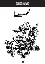
Page 11: ...11 EXPLODEDDRAWING 10230 25...


