10168-10
STEP 5
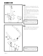
• Remove the 4 M8 x 15mm Button Screws (34), 4 M8
Split Washers (42) and 4 Curved Washers (68) from the
Frame (1).
• While another person holds the Upright (13) near the
Frame (1), connect the Extension Wire (64) to the Reed
Switch Wire (39). Connect the Resistance Cable (23) to
the Lower Cable (29).
• Push the Wires (64, 39) and the Cables (23, 29) into the
Frame (1).
• Insert the Upright (13) into the Frame (1).
• Attach the Upright (13) with 4 M8 x 15mm Button
Screws (34), 4 M8 Split Washers (42) and 4 Curve
Washers (68).
STEP 6
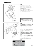
• Attach the Handlebar (50) to the welded metal clamp of
Upper Front Post (13) and secure with Spacer (54),
Decoration Cover (67) and Wing Knob Nut (44).
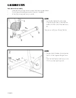
ASSEMBLY STEPS
Caution
: Ensure that cables are not damaged
during assembly or when tightening screws
Caution
: Ensure that cables are not damaged
during assembly or when tightening screws
Summary of Contents for PACE 360
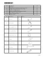
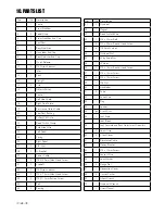
Page 6: ...10168 6 3 HARDWARE LIST ...
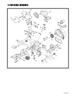
Page 19: ...10168 19 11 EXPLODED DRAWING ...


