TRIVIEW TDR-3604R Installation And Operation Manual Download Page 56


 TDR series Digital Recording System 

Page:  

56


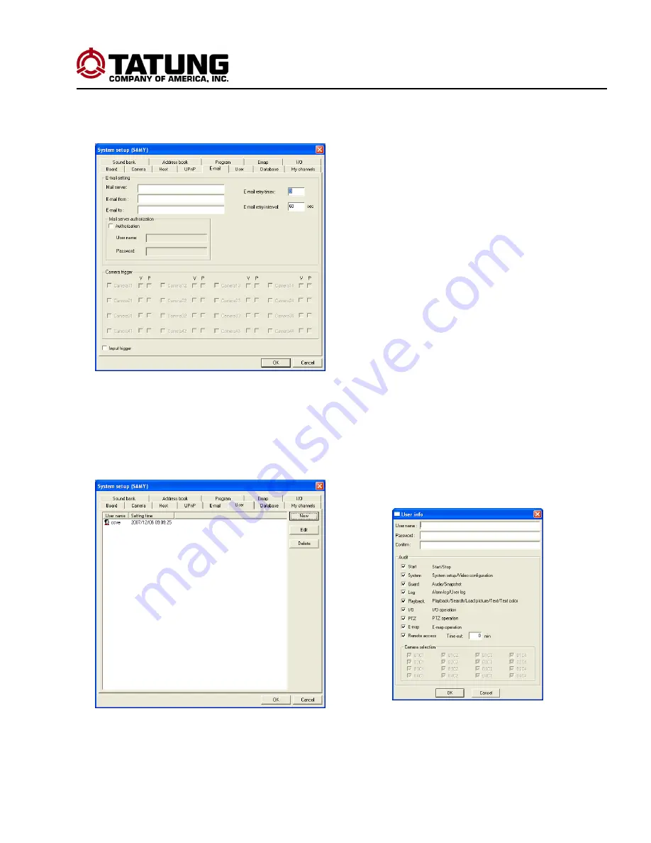
      5. EMAIL SETUP: For installed video capture card. 

     Click on the Email tab as shown and following window will display:


To setup email, fill in the appropriate fields and press OK to save. 

      6. USER SETUP: 

Click on the User tab and the following window will display. Click New setup a new user, or highlight an existing 

user to edit or delete the user.  Click on OK to save. 


Please read each option carefully. Once you have made all your setting options, click OK to save. 


Summary of Contents for TDR-3604R

Page 1: ...TDR 3604R Digital Recording System Installation and Operation Manual TATUNG COMPANY OF AMERICA INC 2850 El Presidio St LONG BEACH CA 90810 USA Tel 310 637 2105 FAX 310 632 3588 www tatungusa com...

Page 2: ...evisions B4 00 Jul 07 First Released B5 00 Apr 08 After 4 channels playback B6 00 Apr 08 Sales Review B7 00 Sep 08 After Engineer Review in red B8 00 Sep 08 After calendar search Save Button B9 00 Jan...

Page 3: ...rds Please refer all servicing to qualified service personnel Do not use liquid cleaners or aerosols for cleaning Do not touch the power cord with wet hands It may generate heat or cause fire The powe...

Page 4: ...2 8 ADVANCE Setup 33 Chapter 4 Recording Live View 35 4 1 Recording Live view mode button definition 36 4 2 Activate the Recording 38 4 3 Mute Control output 38 Chapter 5 Playback 39 5 1 Playback mod...

Page 5: ...V monitor for video monitoring Audio Out 1 RCA connector to connect to an audio monitor VGA Out 1 VGA connector for connecting to a VGA monitor Video Loop Through 4 BNC connectors loop through video H...

Page 6: ...SB Ports 5 Power Key 6 Backup Button 7 Stop cancel Button 8 Record Button 9 Network LED 10 Warning LED 11 Speaker LED 12 Play LED 13 Record LED 14 Power LED 15 Enter Pause Button 16 Increase Faster Bu...

Page 7: ...VGA Output 8 Alarm Output 9 Alarm Input 10 Audio Output 11 Video Output 12 Channel 1 4 Loop Out 13 USB Connector 2 2 Rear Panel Note Do not turn this unit on before all the connections are complete R...

Page 8: ...ng key counter clockwise then lift the rack handle up and pull out the hard drive rack 2 Unlock left corner closest to you or unscrew both back screws and push back the cover to remove the hard drive...

Page 9: ...mode will be defined in the following chapters Note 1 System will try to maximize partition size but no larger than 250 GB Or 500 G 2 It will make a single partition only if the HDD size is less than...

Page 10: ...ess the to accept 4 Always press to save the settings and go previous page or exit from the setup page 5 If a password has been setup it will prompt for the password Please key in the correct password...

Page 11: ...cancel any change and exit out Backup Button Press this button to get into backup mode Playback Button Press this button to get into playback mode Up Button Press this Button to move up Right Shift B...

Page 12: ...uttons 0 to 9 to enter the value directly 4 Press the to accept TIME DISPLAY SETUP DATE 2005 04 28 TIME 14 41 38 TIME ZONE GMT 08 SYSTEM TME ON OFF CAMERA NAME ON OFF MAIN SUB DISPLAY ON OFF NTP CLOCK...

Page 13: ...IME ZONE Setup 1 Select the TIME ZONE submenu and confirm the selection 2 Use or to select the setting of Time Zone For example New York as GMT 5 Houston as GMT 6 Los Angeles as GMT 8 3 Press the to a...

Page 14: ...one at time and confirm it 2 Use or to turn it ON OFF 3 Press the to accept NTP SERVER Setup To set URL name or IP address of the NTP sever 1 Select the NTP SERVER submenu and confirm the selection 2...

Page 15: ...e or use number button 0 9 to input a number 4 Press the to accept ENABLE Setup Enables disables the camera 1 Please refer to Note 1 in Section 3 to select ENABLE submenu 2 Use or to turn it ON OFF 3...

Page 16: ...cept BRIGHTNESS Setup 1 Select BRIGHTNESS submenu 2 Use or to change the value or use 0 9 buttons to input 0 to 255 3 Press the to accept CONTRAST Setup 1 Select CONTRAST submenu 2 Use or to change th...

Page 17: ...to 255 3 Press the to accept HUE Setup 1 Select HUE submenu 2 Use or to change the value or use 0 9 buttons to input 0 to 255 3 Press the to accept VIDEO CONFIGURATION DEFAULT Setup 1 Select VIDEO CO...

Page 18: ...selecting the sensitivity level 1 Select MOTION DETECTION and confirm the selection 2 Use or to turn it OFF or ON by setting the sensitivity from 1 least to 16 strongest 3 Press to accept ALARM SETUP...

Page 19: ...o turn it OFF or turn it ON by setting the time from 100 to 999 Seconds 3 Press to accept MASK 1 4 Setup Sets top left and bottom right corners 1 Select MASK submenu xx yy xx yy 2 Use to change the va...

Page 20: ...D SPEED Setup 1 Select RECORD SPEED submenu 2 Use or to select the speed 1 2 3 5 10 15 30 or use the number buttons 0 to 9 to set the value 3 Press to accept SYSTEM SETUP VIDEO MODE NTSC PAL RECORD SP...

Page 21: ...e SCAN INTERVAL Setup 1 Select SCAN INTERVAL submenu 2 Use or to select the select the time 1 99 in seconds 3 Press to accept AUTO RECORD Setup 1 Select AUTO RECORDING submenu 2 Use or to turn it ON o...

Page 22: ...turn it ON or OFF 3 Press to accept VGA PIP Setup For future upgrade 1 Select VGA PIP submenu 2 Use or to turn it ON or OFF 3 Press to accept Note PIP function is only available for VGA monitor It is...

Page 23: ...pressing the go back to the beginning of the NETWORK setup page NETWORK SETUP SERVER SETUP HOST NAME RT4_________ CONNECT SERVER ON OFF SERVER SERVER PORT 40000 DISCONNECT ALM ON ON ON ON Note To edi...

Page 24: ...UP GET IP AUTO GET IP MANUAL SETUP IP NETWORK SETUP SERVER SETUP HOST NAME RT4_________ CONNECT SERVER ON OFF SERVER SERVER PORT 40000 DISCONNECT ALM ON ON ON ON NETWORK SETUP DNS SETUP GET IP AUTO GE...

Page 25: ...to accept NETWORK SETUP SERVER SETUP HOST NAME RT4_________ CONNECT SERVER ON OFF SERVER SERVER PORT 40000 DISCONNECT ALM ON ON ON ON NETWORK SETUP NETWORK INFO LOCAL IP 192 168 12 105 DNS SERVER 242...

Page 26: ...to select number or use the number buttons 0 9 4 Press to accept SERVER PORT Setup Currently the port is locked and set for 40000 for now 1 Select SERVER PORT submenu 2 Use or to shift and select the...

Page 27: ...for LAN and the second port is for WAN LISTEN PORT Setup 1 Select the LISTEN PORT submenu 2 Use or to shift and select the character field 3 Use or to select number or use the number buttons 0 9 4 Pr...

Page 28: ...DHCP WAN mode NETWORK SETUP CONNECTION LISTEN PORT 50000 50000 MODE LAN GET IP MANUAL GET IP LOCAL IP 192 168 1 15 NET MASK 255 255 255 0 GATEWAY 192 168 1 1 NETWORK SETUP CONNECTION LISTEN PORT 50000...

Page 29: ...Y submenu 2 Use or to shift and select the character field 3 Use or to select number or use the number buttons 0 9 5 Press to accept NETWORK SETUP CONNECTION LISTEN PORT 50000 50000 MODE DIAL UP USER...

Page 30: ...TWORK SETUP DNS SETUP There are two ways to get an IP address Auto and Manual NETWORK SETUP DNS SETUP GET IP AUTO GET IP MANUAL GET IP NETWORK SETUP DNS SETUP GET IP AUTO GET IP NETWORK SETUP DNS SETU...

Page 31: ...Create or change a password SETUP Setup To allow a specific user to setup the DVR remotely DOWNLOAD Setup To allow a user to download data remotely OUTPUT Setup To allow a user to control the relay ou...

Page 32: ...1 4 BUZZER Setup To turn DVR SPEAKER ON OFF Will be indicated on the front panel as SPKR LED The speaker will sound if the hard drive has a problem INPUT 1 4 Setups Trigger Type LOW normally closed HI...

Page 33: ...n that state after logging out Select LOGOUT and confirm the selection LOGOUT AND RECORD This will logout and put the system in a recording state Select LOGOUT AND RECORD and confirm the selection PRO...

Page 34: ...ect UPGRADE FIRMWARE and confirm the selection 4 The system will update the firmware automatically and reboot after the update complete LOAD DEFAULT Recording must be stopped first Select LOAD DEFAULT...

Page 35: ...tem status will also display Camera name system time and HDD status Date Time display can be set on 4 SYSTEM TIME in TIME DISPLAY SETUP Ch1 Ch2 Ch3 07 03 14 14 50 05 Ch4 HDD HDA1 FREE 100 3 G TTL 286...

Page 36: ...se button Disabled Enter or Pause Disabled Record Button Press this button to activate recording if recording has been stopped Stop Button Press this button to cancel any change and go back to live mo...

Page 37: ...4 Buttons Press one of these buttons to enlarge that channel in full display other channels continue to record 9 Quad Button Press this button will view the quad display To 5 to 8 buttons Disabled Lef...

Page 38: ...or recording modes press to get to the mute control output menu This control function can force stop all the audio and alarm output immediately MUTE Setup Select MUTE and confirm the selection OUTPUT1...

Page 39: ...to playback a single frame Record Button It has 2 functions 1 Activate the recording after recording has been stop 2 If both playback and recording live Display are active press this button is to swit...

Page 40: ...ayback to skip forward 30 seconds 0 Seq Buttons Disabled to 1 thru 4 Buttons Display each channel full screen 9 Quad Button Go back to 4 channel quad display to 5 to 8 buttons Disabled Left Shift Butt...

Page 41: ...2 Use or to shift and select the field 3 Use or to select number or use the number buttons 0 9 4 Press to accept 5 Select START TIME and confirm the selection 6 Follow the step 2 to 4 to set the Star...

Page 42: ...t the record you want to play then press or key to play it 4 channel playback will be displayed PLAYBACK DATE LIST 2009 07 25 HDA1 2009 07 24 HDA1 2009 07 23 HDA1 2009 07 22 HDA1 DATE LIST 2009 07 24...

Page 43: ...Fast Forward Pressing during playback fast forwards 30 seconds each time the button is pressed Playback Slow speed Press to slow down the playback by 1 6 and 1 8 Playback Fast speed Press speed up th...

Page 44: ...will get the following Alarm Log Date list 1 Press button to select date and HDD 2 Press and file list menu will display 3 Use to choose the file and press to select and play it ALARM LOG DATE LIST 2...

Page 45: ...ote Please format your USB backup device to FAT 32 file system before you start to backup the data 7 3 Backup the data 1 During Recording Live view press to enter the File Backup Date List menu as Fig...

Page 46: ...t then hit to confirm your selection The process will start and backup data to USB device You will receive a BACKUP OK message if all is correct otherwise you will get an error prompt and should resta...

Page 47: ...e done manually if needed 8 1 Network Setup Triview Server Triview Main Control Software 7 Triview Player Triview Main Control Software Triview Player 7 DVR1 DVR2 NETWORK SWITCH Note The Triview Serve...

Page 48: ...system server IP will be 211 172 12 34 if it is through internet to connect to server If it is under the same LAN network then the IP address is 192 168 1 11 TDR 3604R DVR and Triview Main Control So...

Page 49: ...ar buttons Level 1 Level 2 Next level Description File Login For system setting privilege Logout To logout Start Server To start the server Shutdown Sever To shutdown the server Auto Start To start se...

Page 50: ...is not set to automatically start This will allow other TDR 3604R DVRs and other Triview system to connect to network TDR 3604R DVR System For a detailed description please refer to Chapter 3 2 5 Netw...

Page 51: ...remote access Auto scan System setup Log check button Map button Audio mute button Displays or hides the function panel buttons Connected Host HDD Free Space Channel Display Current Time Display From...

Page 52: ...anel Buttons Description Switches between Host panel and My Channel panel Switches between Host panel and My Channel panel Host panel My channel panel PTZ panel Output panel selection PTZ controller H...

Page 53: ...once you will need to hit the Escape Key and input your user name and password Triview window will pop up Enter System Setup for the Triview program by clicking on the SET button in the set up menu No...

Page 54: ...he following window will display To setup a new board select options or fill in each field then click on the OK to save 2 CAMERA SETUP The involved DVR must be connected and selected Click on the Came...

Page 55: ...n below and the following window will display Please read each option carefully Once you have made all your setting options click OK to save 4 UPnP SETUP Enables disables UPnP and sets Local LAN WAN a...

Page 56: ...display To setup email fill in the appropriate fields and press OK to save 6 USER SETUP Click on the User tab and the following window will display Click New setup a new user or highlight an existing...

Page 57: ...m or sound HDD space is low Click on OK to save 8 MY CHANNELS SETUP Click on the My channel tab and the following window will display Click on New to add a channel or click on an existing channel to e...

Page 58: ...System Page 58 9 SOUND BANK SETUP Click on the Sound bank tab and the following window will display Click on New to add sounds the New sound file window will appear or highlight an existing file Edit...

Page 59: ...the system running the server then the communication port default 40000 11 PROGRAM SETUP Click on the Program tab and the following will display Click on New to configure a new program Configure all...

Page 60: ...o prompt and see windows below for reference After clicking on the Edit button click on the add level button on the upper left corner of the window The cursor will turn to a Move the cursor to the des...

Page 61: ...the newly added level location You can edit delete or close the existing Emap 13 ADD MOVE Camera PC Level on the MAP Highlight the map and click New or Edit The Emap edit window will display Example o...

Page 62: ...ve the cursor to the desire location and click the left mouse button to finish the camera location setup A window will pop up for you to assign the camera to the host and camera number To move a camer...

Page 63: ...addition to the preset alarm functions as recording cameras activate alarm functions or an alarm has been triggered if you click the Emap button the triggered camera will display in the Emap This make...

Page 64: ...up when motion is detected When alarm is triggered 16 I O SETUP To control speed dome cameras connected to PC capture card Click on the I O tab and the following window will display To setup a new PTZ...

Page 65: ...ple If network settings are correct connected will appear in the Status column This means you are now connected with the Server program Now click OK You can configure the host tab to have it connected...

Page 66: ...ing System Page 66 Press and the following Remote Channel Select will display as follows Choose whether to record or monitor each channel and click OK The system will then display your cameras based o...

Page 67: ...e view you can right click the channel to preview the previously recorded data you can choose previous 1 2 or 3 etc minutes Example below is right click on channel 4 then preview button show up Exampl...

Page 68: ...ng System Page 68 Window below shows after selecting the previous minutes and click on OK button 8 3 Remote File Search Click and then click the File mode button You can now search the database from t...

Page 69: ...double click the file and choose the start end channel to playback In addition you are capable to play multi channels of the same DVR at the same time See example in window below Once you are in the f...

Page 70: ...fast and easy search on any channel on any DVR in the network in within minute at any specific of 1 hour period of any selected recording date To activate this search the involved DVR must be connecte...

Page 71: ...fic area section that area remains light blue Window below shows that on Aug 08 2008 all channels have full recorded data and Aug 11 channels 1 4 only have data from 01 10 o clock Select the channel p...

Page 72: ...points which has been searched already The red mark indicates the current starting point to search After clicking on the started minute it will search for file and start playing as shown in window be...

Page 73: ...tc It is capable to detect if the file has been tampered Playback Message area Displays all the information for the playback files include host name time and status Host name and time zone Recording d...

Page 74: ...lay during fast or slow playback the playback speed returns to normal Pause Pauses the current video To continue the playing again click again or click the playback button Backward Search Rewinds the...

Page 75: ...or the recording Caption Color Changes the color of the caption useful for different video backgrounds if the text is difficult to see Authenticate button To check and see if the file has been tampere...

Page 76: ...figuration where you can adjust the images Brightness Contrast Saturation or Hue for better image effect You can also access the Motion Search Setup enable Motion Search enable Continuous Playback and...

Page 77: ...ed Converting Files Click Convert and the Video Compression dialog will appear Select an AVI compression format to use to proceed with the converting of the files Click OK After the conversion the fil...

Page 78: ...Problem Completely distorted picture Solution Check the monitor and camera Make sure the video cable is connected to the correct port and no other interference is on the line Problem No Audio Solution...

Reviews: