8
GB
9
GB
OPERATION
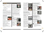
The angle of bevel can be read on the scale.
There are “click” stops at 22.5°, 45°
and 67.5° to allow quick setting to these
common angles.
BEVEL GUIDE LOCKING KNOB
Loosen the bevel guide locking knob (10)
before adjusting the bevel angle and retighten
it when you have made the adjustment.
PERSPEX WINDOW
The three lines on the
window (11) in the bevel
guide (9) show the
position of the centre
of each drill bit and
the mid-point between
them. They are used
as a guide when drilling to marks made on
the work piece to designate the desired
position of the holes.
FACE PLATE
Hold the face plate (12) firmly and flush
against the work piece when drilling.
DEPTH GUIDE
The drilling depth can
be adjusted between
0 and 1.56" by setting
the position of the
depth guide (14) to
the desired value.
DEPTH GUIDE LOCKING KNOB
Loosen the locking knob (14), move the
depth guide (13) and retighten the locking
knob (14).
ZERO MARKER
The position of the
zero marker (15) can be
adjusted using a small flat
screwdriver to prise it to
the left or right.
EDGE GUIDE
The edge guide (16)
can be used to adjust
the distance of the
holes from the edge
of the work piece.
Continuous adjustment is possible between
approximately 0.28" (7mm) – 1.65" (42mm).
EDGE GUIDE RATCHET KNOB
The ratchet knob (17) allows fine
adjustment of the movement of the
edge guide.
EDGE GUIDE
LOCKING KNOB
Loosen the locking knob
(18), move the edge
guide (16) and retighten
the locking knob (18).
Do not attempt to turn the ratchet
knob (17) whilst the locking knob (18)
is in the tightened position. It could
damage the ratchet mechanism.
DRILL BITS
The tool is supplied with two drill bits
each of 0.24", 0.31" and 0.39" ( 6mm, 8mm
and 10mm).
HEX KEY
This key is used to loosen and tighten the
clamping screws (5).
ADJUSTING THE ZERO POSITION
After replacing the drill bits, it is necessary
to reset the tool so that the depth guide
(13) reads correctly.
1. Loosen the bevel guide locking knob (10)
and swivel the bevel guide (9) fully open
(e.g. 90°).
2. Tighten the locking knob (10)
3. Loosen the depth guide locking knob (14).
4. Place the bottom edge of the face plate
(12) against a rigid surface and push the
tool forward until the tips of the drills are
flush with the surface of the face plate.
5. Push the depth guide as far as possible
in the direction away from the face plate
and tighten the locking knob (14).
6. Adjust the position of the zero marker
(15) so that it aligns with the zero
position on the depth guide.
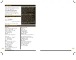
ACCESSORIES
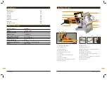
The Triton TC850DWL Dowel Joiner is
supplied with the following accessories
as standard:
• 2 each drill bits of 0.24", 0.31" and 0.39"
( 6mm, 8mm and 10mm).
• Hex key
• Storage case
• Instruction Manual
UNPACKING
Due to modern mass production
techniques, it is unlikely that your Triton
Power Tool is faulty or that a part is
missing. If you find anything wrong, do not
operate the tool until the parts have been
replaced or the fault has been rectified.
Failure to do so could result in serious
personal injury.
ON/OFF SWITCH
Push the on/off switch
(1) forward and up over
the latching ramp to
lock the switch on.
To turn the tool off,
press the rear of the
switch and lift it over
the latching ramp.
MOTOR HOUSING
Take care not to cover the ventilation grills
when holding the tool whilst drilling.
CARBON BRUSH CAPS
To gain access to the carbon brush and
spring sets, unscrew the two brush cap
covers (3).
BIT HOLDER
To replace or change
drill bits, rotate the bit
holders (4) until the bit
clamping screws (5) are
accessible from the top
of the machine. Loosen
the clamping screws (5)
with the hex key (20) provided.
Remove the unwanted drill bits and insert
the replacement bits (6) with the flat of the
shank under the clamping screw.
Tighten the clamping screws and check that
the bits are firmly secured.
After replacing drill bits it is necessary
to reset the zero position as detailed in
“Adjusting the zero position”.
BIT CLAMPING SCREW
When tightening a bit clamping screw, take
care that the flat of the shank of the drill is
directly under the screw.
DRILL BIT
The tool is supplied with two each of 6mm,
8mm and 10mm drill bits.
DUST
EXTRACTION
PORT
Always attach a suitable
workshop vacuum or
dust collector to the
dust extraction port (7).
HANDLE
Hold the tool with two
hands during operation.
One hand on the
housing (2) and the
other on the handle (8).
BEVEL GUIDE
The bevel guide (9)
can be swiveled
through 90° to suit
the angle at which the
dowel holes are to
be drilled in the work
piece. It is commonly
used when working on
a mitred edge.
FUNCTIONS
Functions
Functions
Summary of Contents for TC850DWL
Page 14: ...26 F 27 F...
Page 15: ......


