Triton ARGO G60 Installation Manual Download Page 28

B-5

A

ppendix

 B - ATM i

nsTAllATion


for

 A

ccessiBiliTy

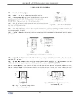
(a)   Reach Depth Not More Than 10 inches (255 mm).

  Where the reach depth to the operable parts of all controls as measured 

from the vertical plane perpendicular to the edge of the unobstructed clear floor space at the farthest protrusion of the automated 

teller machine or surround is not more than 10 inches (255 mm), the maximum height above the finished floor or grade shall be 

54 inches (1370 mm). 

b)   Reach Depth More Than 10 inches (255 mm).

  Where the reach depth to the operable parts of any control as measured 

from the vertical plane perpendicular to the edge of the unobstructed clear floor space at the farthest protrusion of the automated 

teller machine or surround is more than 10 inches (255 mm), the maximum height above the finished floor or grade shall be as 

follows: 

ACCESSIBILITY SPECIFICATIONS

REACH DEPTH

MAXIMUM HEIGHT

Inches

Millimeters

Inches

Millimeters

10

255

54

1370

11

280

53 1/2

1360

12

305

53

1345

13

330

52 1/2

1335

14

355

51 1/2

1310

15

380

51

1295

16

405

50 1/2

1285

17

430

50

1270

18

455

49 1/2

1255

19

485

49

1245

20

510

48 1/2

1230

21

535

47 1/2

1205

22

560

47

1195

23

585

46 1/2

1180

24

610

46

1170

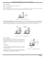
(3)   Forward and Parallel Approach.

   If both a forward and parallel approach are possible, operable parts of controls shall be 

placed within at least one of the reach ranges in paragraphs (1) or (2) of this section.

4)  Bins.

   Where bins are provided for envelopes, waste paper, or other purposes, at least one of each type provided shall comply 

with the applicable reach ranges in paragraph (1), (2), or (3) of this section. 

EXCEPTION:

  Where a function can be performed in a substantially equivalent manner by using an alternate control, only one of 

the controls needed to perform that function is required to comply with this section. If the controls are identified by tactile markings, 

such markings shall be provided on both controls. 

4.34.4  Controls. 

  Controls for user activation shall comply with 

4.27.4


(Operation). 

4.34.5  Equipment for Persons with Vision Impairments. 

  Instructions and all information for use shall be made accessible to 

and independently usable by persons with vision impairments. 

(20) 


Where automated teller machines (ATMs) are provided, each ATM shall comply with the requirements of 

4.34 (Automated 

Teller Machines)

 except where two or more are provided at a location, then only one must comply. 

EXCEPTION:

  Drive-up-only automated teller machines are not required to comply with 

4.27 (Controls and Operating Mecha-

nisms)

 and 

4.34.3 (Reach Ranges). 

Summary of Contents for ARGO G60

Page 1: ...B STREET LONG BEACH MS 39560 PHONE 800 259 6672 FAX 228 868 9445 2014 Triton All Rights Reserved TRITON logo is a registered trademark of Triton Systems of Delaware LLC TDN 07103 00053 AUTOMATED TELLE...

Page 2: ...ism into the unit until the unit is bolted down to the ground If the mechanism is installed prior to bolting the unit down the unit could tip over and personal injury could occur Follow the installati...

Page 3: ...UNITS 12 CABINET INSTALLATION 13 UNPACK ATM 14 MARK DRILL MOUNTING HOLES 15 INSTALL STANDARD ANCHORS BOLT ATM TO FLOOR 16 ROUTE AC POWER AND COMMUNICATION CABLE 17 APPENDIX A SOFTWARE LICENSE AGREEMEN...

Page 4: ...unit are met 9 Install the unit at a height which meets the ADA DDA CSA accessibility regulations for the state country installed Refer to Appendix B TOOLS REQUIRED Torque wrench adjustable to at leas...

Page 5: ...Plan operator training exercises optional 10 Install communication lines and test 11 Ensure installation accessories are available TEMPERATURE HUMIDITY 1 The ATM will operate over a range of temperat...

Page 6: ...ax machines Point of Sale devices Proximity to Interference Sources The telephone line must not be in close proximity to noisy devices that could induce interference into the ATM communications channe...

Page 7: ...4 972mm 5 Bill Tray 27 3 16 690mm Feature Height Customer Access Dimensions CABINET FRONT VIEW CABINET SERVICE AREA DIMENSIONS Dimension Preferred Area Minimum Area A 26 660 24 1 2 622 B 33 9 16 853...

Page 8: ...8 ARGO G60 INSTALLATION MANUAL CABINET DIMENSIONS SIDE VIEWS Left Left Right Right...

Page 9: ...9 ARGO G60 INSTALLATION MANUAL CABINET TOPPER CABINET SIGN AREA BACKLIT GRAPHIC Rear Side Front...

Page 10: ...10 ARGO G60 INSTALLATION MANUAL CABINET FOOTPRINT...

Page 11: ...11 ARGO G60 INSTALLATION MANUAL CABINET DECAL AREA SUGGESTED DECAL AREA VISIBLE DECAL AREA...

Page 12: ...hen replacing older TritonATMs with theARGO G60 you may be able to use holes already drilled to install the ATM See the table below for corresponding hole sites CABINET ARGO G60 9100 with SDD deep ver...

Page 13: ...RGO G60 ATM is designed for INDOOR use only WARNING DO NOT APPLY POWER TO THIS TERMINAL UNTIL THE INSTALLA TION IS COMPLETE WARNING Do NOT install the mechanism into the unit until the unit is bolted...

Page 14: ...accessory box is shipped inside the cabinet enclosure Open and inspect the contents Check the contents against the enclosed packing list and report any missing parts to Triton 11 Unbolt the ATM from t...

Page 15: ...s will help guide the masonry bit that will be used to drill the anchor bolt holes in the next step Mark Drill Mounting Holes 5 Use a portable vacuum cleaner to remove any dust or debris that may have...

Page 16: ...ting by aligning the base over the four holes drilled in the previous procedure 3 Place an anchor bolt through the cabinet base and into one of the mounting holes Use a ball peen hammer to tap the bol...

Page 17: ...tighten down firmly Use anchor bolt in each mounting hole Hammer bolts snuggly into drilled holes NOTE Before you start unlock and open the control panel Verify that the power switch on the unit s pow...

Page 18: ...s then use an 11 32 driver to tighten the nuts This unit may be equipped with more than one power cord Disconnect All Power Cords prior to Servicing For continued fault protection follow the correct v...

Page 19: ...or on one end and molded plug on the other end 3 Certified for country of installation 4 Rated minimum H05VV F with minimum 0 75 mm2 except where specific countries require 1 0 mm2 conductors 5 Maximu...

Page 20: ...APPENDIX A SOFTWARE LICENSE AGREEMENT COMPLIANCE EMISSION STATEMENTS...

Page 21: ...icense to use theATM Software but only in connec tion with the operation of thisATM subject to the terms and restrictions set forth in this LicenseAgreement You are not permitted to use theATM Softwar...

Page 22: ...ATIVEHASBEENADVISEDOFTHEPOSSIBILITYOFSUCHDAMAGES ORFORANY CLAIMBYANYTHIRDPARTY YOURSOLEREMEDYAGAINSTTRITONFORDEFECTIVEPERFORMANCEOFTHEATMSOFTWARE WILLBE LIMITED EXCLUSIVELYTO REPAIR OR REPLACEMENTOFTH...

Page 23: ...ith the instruction manual may cause harmful interference to radio communications Operation of this equipment in a residential area is likely to cause harmful interference in which case the user will...

Page 24: ...Appendix B ATM Installation for Accessibility...

Page 25: ...specified clear floor or ground space shall be positioned for either forward or parallel approach to an element 305 6 Approach One full unobstructed side of the clear floor or ground space shall adjoi...

Page 26: ...aximum Where the reach depth exceeds 20 inches 510 mm the high forward reach shall be 44 inches 1120 mm maximum and the reach depth shall be 25 inches 635 mm maximum Figure 308 2 2 Obstructed High For...

Page 27: ...ed States may also have accessibility codes These codes may be more restrictive than the federal guidelines Please verify this with the state where the ATM is to be installed prior to installation For...

Page 28: ...1180 24 610 46 1170 3 Forward and Parallel Approach If both a forward and parallel approach are possible operable parts of controls shall be placed within at least one of the reach ranges in paragrap...

Page 29: ...ar floor or ground space for a wheelchair shall adjoin or overlap an accessible route or adjoin another wheelchair clear floor space If a clear floor space is located in an alcove or otherwise confine...

Page 30: ...required Figures 4d Clear Floor Space in Alcoves 4 2 4 3 Surfaces for Wheelchair Spaces Clear floor or ground spaces for wheelchairs shall comply with 4 5 Ground and Floor Surfaces 4 2 5 Forward Reach...

Page 31: ...no less than 9 inches 230 mm above the floor Fig 6 a and 6 b If the side reach is over an obstruction the reach and clearances shall be as shown in Fig 6 c Figure 6a Parallel approach side reach Figu...

Reviews: