Appropriate
fitting
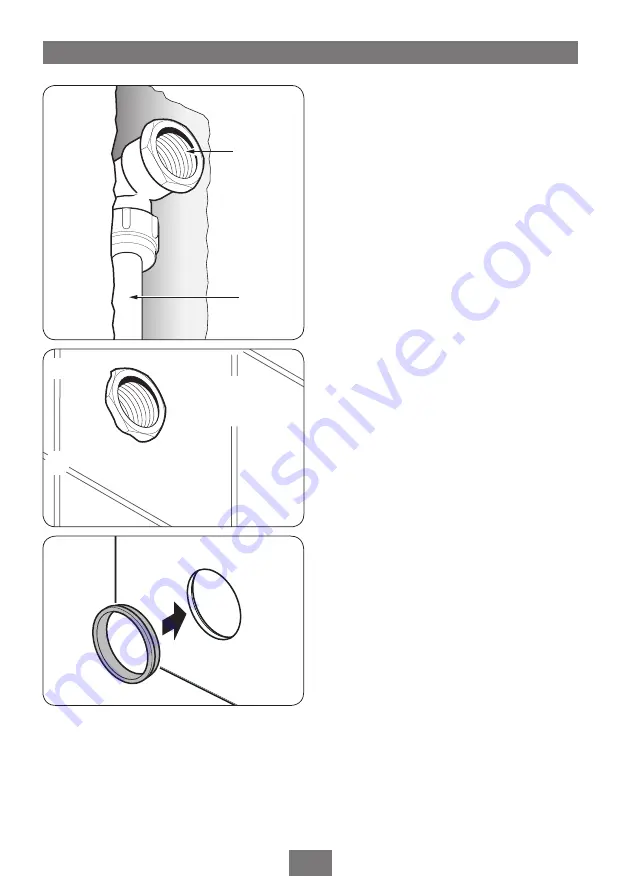
Water pipe
Fig.12
Dual control thermostatic mixer
10
FITTING THE FIXED HEAD
PIPEWORK
Complete the outlet pipework, ending in a
½” BSP x 15mm female thread elbow
(fig.10)
.
Finish the wall so that it is flush with the fitting
(fig.11)
.
Note:
This fitting is not supplied as variations
in installations require the selection of the most
suitable fitting.
MAKING GOOD
Fit the tiling shroud over the mixer body and
make good the wall, tiling etc. and around the
fixed head outlet.
Note that if the tiles are accurately cut to match
the profile of the shroud, then the faceplate will
seal around the hole in the tiles, and the valve
unit can be serviced without the need to break
any tiles.
Make sure the grout lines are flush with the tiles
in order to provide a smooth sealing surface for
the face plate.
FITTING THE FACEPLATE AND
CONTROLS
Insert the rubber trim seal into the temperature
opening of the face plate
(fig.12)
.
Fit the face plate over the valve controls and
slide tight up to the wall. Make sure the rubber
seal stays in place as it slides over the trim. A
smear of liquid soap on the seal will ease this
procedure.
The face plate incorporates a silicon sponge
backing that seals against a smooth wall.
Fitting the temperature control
Temporarily fit the temperature control knob
onto the splined adaptor
(fig.13)
.
DO NOT secure with the grub screw until
the commissioning procedure is complete.
Fitting the On/Off flow control
Insert the ‘O’ ring seal into the recess in the
back of the threaded trim ring
(fig.14)
. Screw
the threaded trim ring onto the On/Off spindle
until it engages into the face plate opening.
Fig.10
Fitting should
be flush with
the finished wall
Fig.11


