USER'S MANUAL
CAN bus LCD Display
TRI66.003 ver 2
10 April 2011
4.4
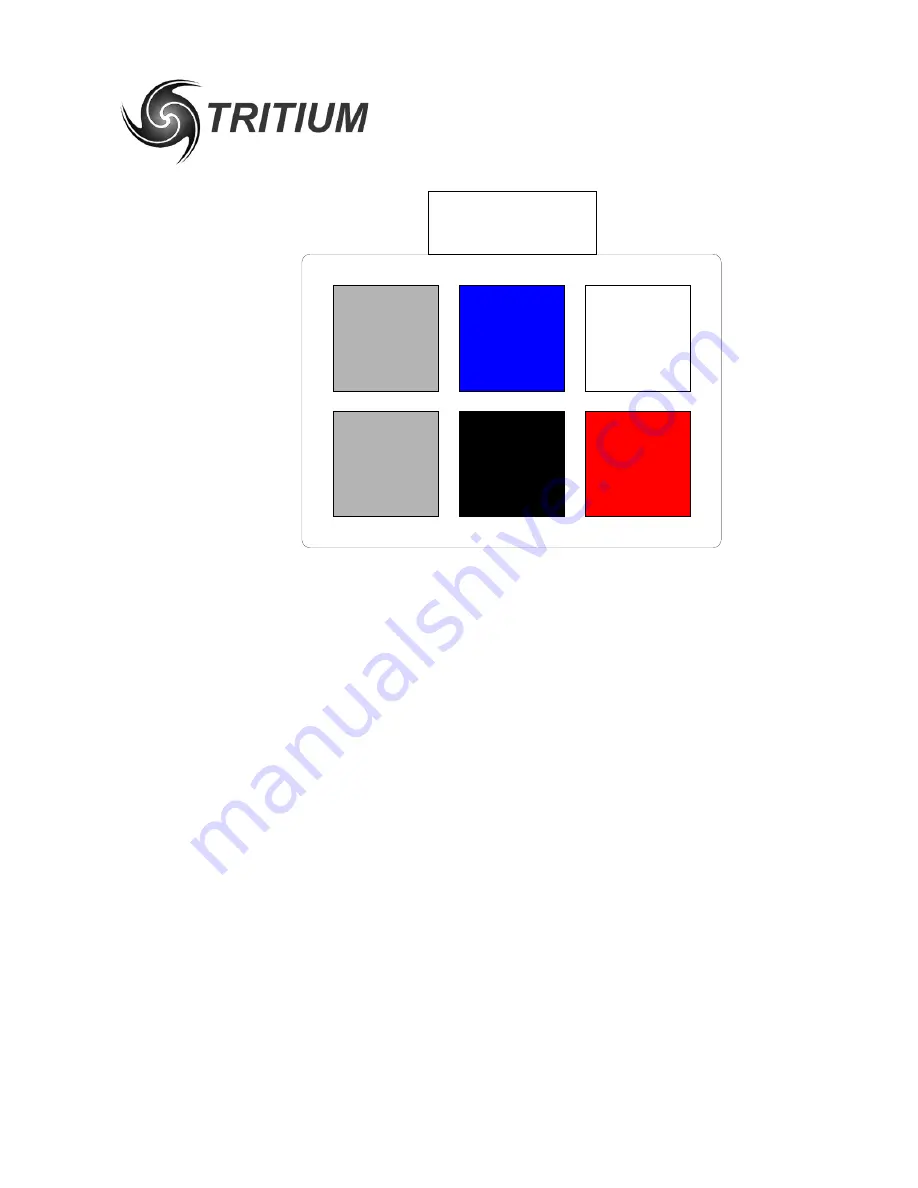
CAN SHIELDING
If the recommended braided shield is used in the cable, then terminate it to the
SHIELD pin (lower-left corner on the connector) on both CAN IN and CAN OUT
connectors on each device.
On
one device only
in the network, instead of using the SHIELD pin, terminate
the shield to the SHIELD GROUND pin (upper-left corner on the connector) on
both CAN IN and CAN OUT connectors, to ground the shield for the entire network
at this single point. The usual place to do this is where power is fed into the
network, typically at Tritium's
EV Driver Controls
product.
4.5
CAN TERMINATION
To implement the required 120 Ohm termination resistor at each end of the CAN
bus, plug a connector into the unused CAN connector on the last device at each
end of the network with a resistor crimped into the appropriate locations.
4.6
COMMUNICATIONS
The CAN standard does not specify high-level message protocols. Tritium devices
use a custom protocol, outlined in the communication specification document for
each device.
By default, each device operates at 500 kbits/second, one step below the
maximum possible data rate of 1 Mbit/second, and comes programmed from the
factory with a CAN base address that will allow it to work without problems with
other Tritium devices. Currently, modifying the data rate or CAN base address
requires reprogramming the microcontroller, although hardware support is
provided to allow updates over the CAN bus in the future.
5 of 7
SHIELD
GROUND
SHIELD
GROUND
CAN-H
+12V
CAN-L
(BARE)
(WHITE)
(BLUE)
(BARE)
(RED)
(BLACK)


