

23.
If connecting rod is not in the down position plug unit in and cycle unit to get connecting rod into down
position.
24.
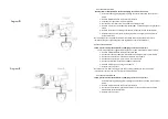
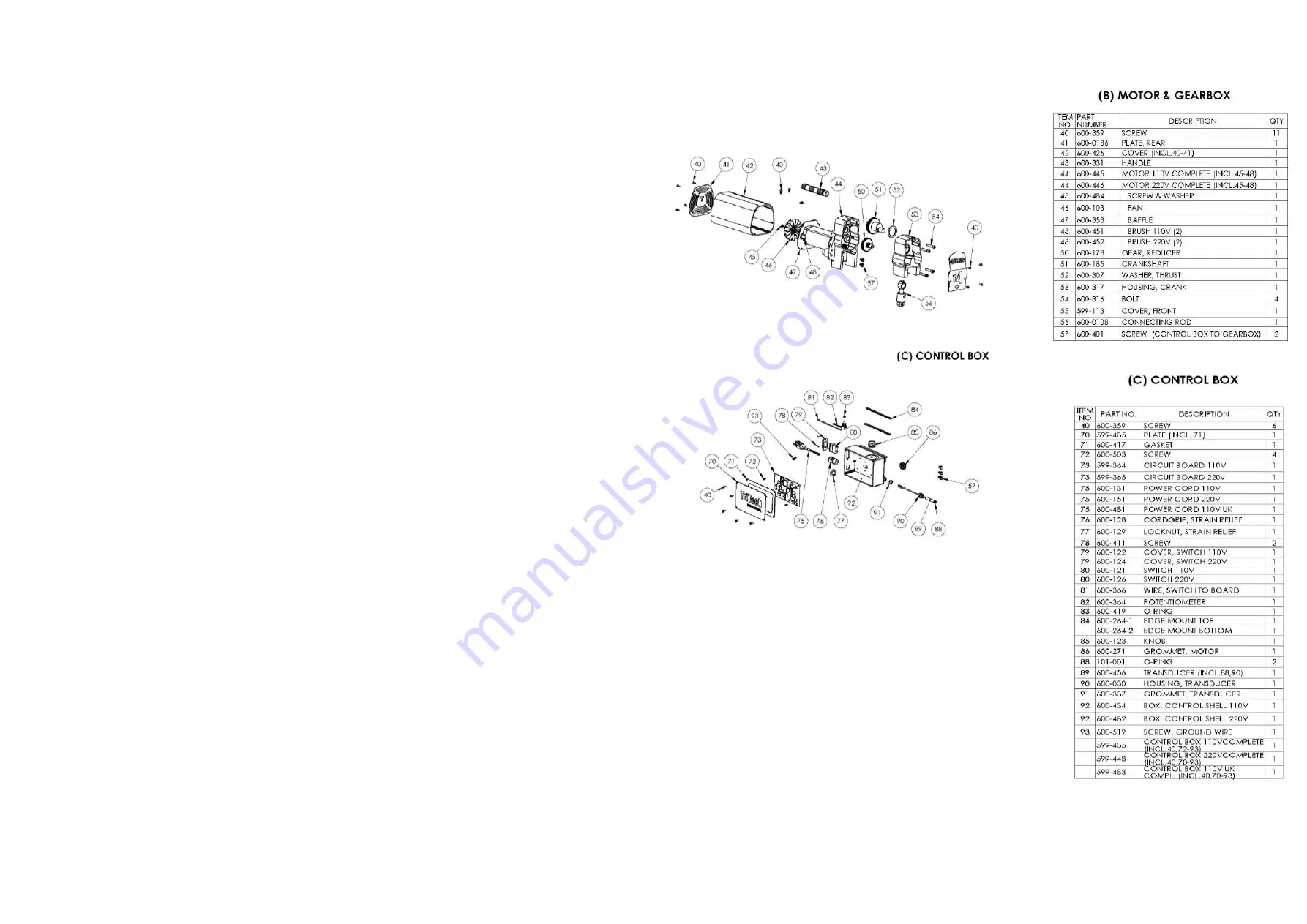
With piston slots aligned slide pump/filter manifold onto connecting rod #56 Diagram “B”. Push
pump/filter manifold towards crank housing # 53 to line up dowel pins then thread mounting bolts #25
through pump filter manifold and thread into crank housing #53. Tighten firmly with5/16” Hex wrench.
25.
Reattach transducer #30 to the back of pump/filer manifold.
26.
Reinstall crankshaft cover plate #55 with 4 screws #40. See diagram “B”.
27.
Reattach suction set.
28.
Pour Trilube through slot in cover plate #55, diagram “B”.
REPLACE BY-PASS VALVE
1.
To replace the pressure relief valve #27 knock pin #29 through black handle #28.
2.
Remove black plastic handle and cap with indexing pin which exposes pressure relief valve.
3.
Using a 3/4” open end unthread by pressure relief valve. Inspect. Replace if worn.
REPLACE FILTER
1.
To replace the paint filter remove filter bowl #1 from fluid manifold by unthreading counter
clockwise.
2.
Remove filter #3 and spring support #4. Most times filter can just be cleaned but if damaged replace.
REPLACE TRANSDUCER
1.
To replace transducer hold wire tube of #31 with plyers, unthread transducer housing #30 from
pump/filter manifold.
2.
Remove mounting screws # 25.
3.
Remove 4 screws for crank housing cover plate # 55.
4.
With a flat blade screwdriver pry pump/filter manifold downward till it clears locating pins and slide
forward but do not remove.
5.
Remove 4 screws #40 and Control box cover plate #70.
6.
Unplug transducer from circuit board. See diagram “B”.
7.
Guide transducer wire out of control box.
8.
To replace guide replacement transducer through grommet #91 and reconnect to circuit board.
9.
Thread transducer into pump/filter housing.
10.
Replacement of transducer requires no calibration of pressure control. To ensure new transducer
functions properly follow Start up procedure.
Summary of Contents for 200-517
Page 6: ......


