background image

5

Setting the RAID Mode

Installation Instructions

When Powered Off:

1.  Install the hard drives in the enclosure according to the installation instructions in 

this manual, but do not power on the unit.

2.  By default, the dip switches on the back of the unit are both set to the OFF (Up) 

position, which will display the hard drives in 

Normal

 mode.

3.  Set the dip switches on the back of the unit according to the desired mode. See 

the RAID Mode section in this manual for each mode’s dip switch configuration. 


Note: 

When changing from RAID 1 mode to another mode, you must first switch to RAID 0 

mode. Once set to RAID 0 mode, you can change to any other mode.

4.  After setting the dip switches accordingly, power on the unit.
5.  After a couple of seconds, your drives will be configured according to the mode you 

have selected. The new drive will not be formatted, and will need to be formatted 

using your computer’s Disk Management utility.

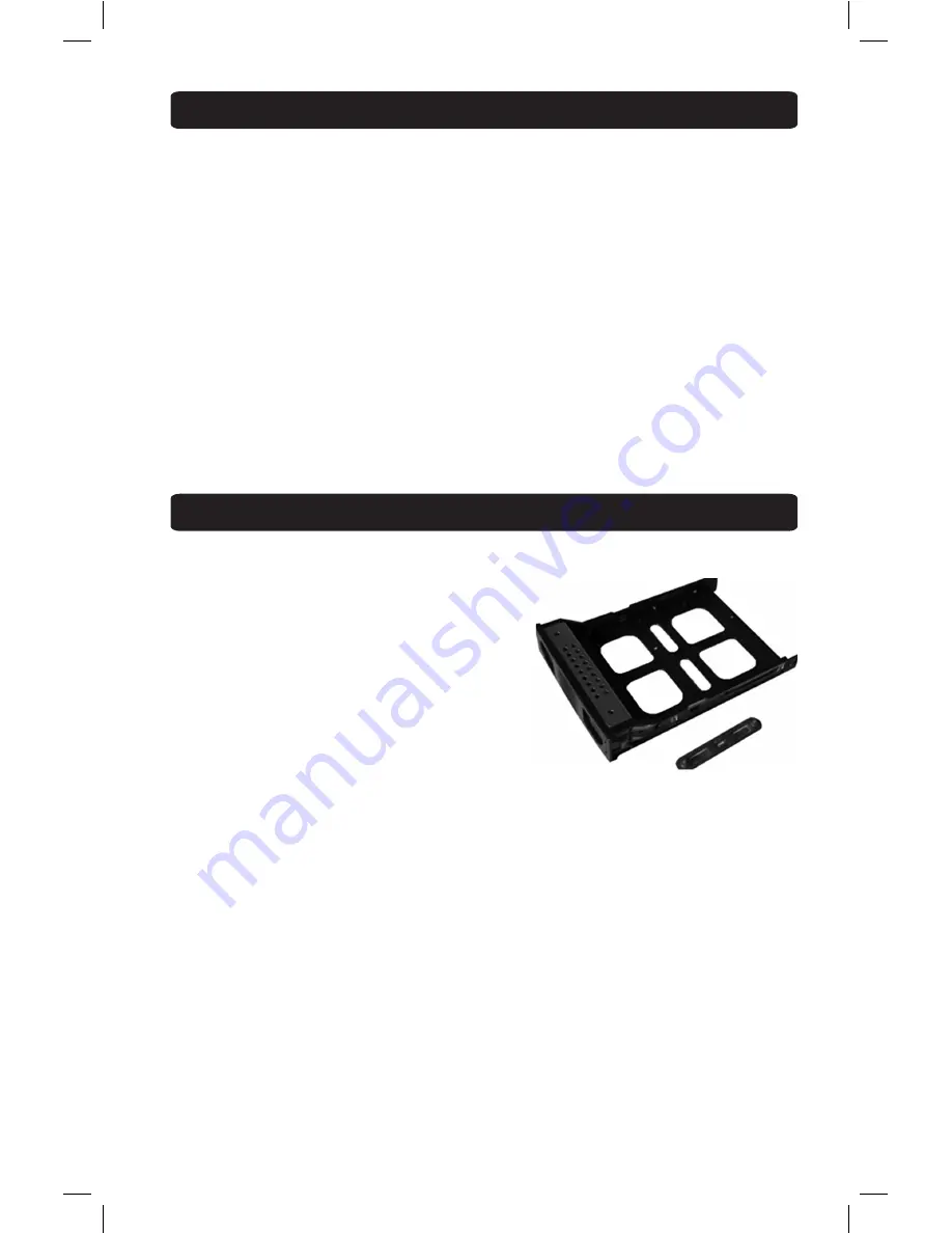
1.  Remove a tray by pressing down the release tabs on its front and pulling it from the 

enclosure.

2.  Remove the side snaps from each side of  

the tray.

3a.


For a 

3.5” HDD –

 Place the hard drive so that 

the SATA connector faces the rear, and the 
screw holes rest on top of the plastic pillars 
located on the side of the tray. Re-insert the 
side snaps on each side of the tray to secure 
the drive in place.

3b. For a 

2.5” HDD –

 Place the hard drive so that 

the SATA connector faces the rear, lining up the screw holes on the bottom of the 
drive with those on the tray. Secure the drive to the tray using the included screws.

4.  Fully insert the tray into the enclosure until it locks into place.
5.  Repeats steps 1 through 4 to install a second hard drive.
6.  Connect the enclosure to your computer using the included USB 3.0 cable.
7.  Connect the included power supply to the enclosure, and plug it into a Tripp Lite 

Surge Suppressor, Power Distribution Unit (PDU), or Uninterruptible Power Supply 
(UPS).

8.  Press the power button on the front of the enclosure to turn power to the unit on. 

The Blue Power LED under the button will illuminate to indicate the unit is powered 
on. The Blue LEDs on the right front of each hard drive tray will illuminate solid to 
indicate the drive is functioning properly. They will blink to indicate that RAID mode 
has crashed or errors have occurred during RAID rebuilding. The Red LEDs on the 

right front of each hard drive tray will blink to indicate that data transfer is taking 
place.

step 2

13-10-121-9332DF.indd   5

10/25/2013   2:43:04 PM

Summary of Contents for U357-002

Page 1: ... o m w a r r a n t y 1111 W 35th Street Chicago IL 60609 USA www tripplite com support Copyright 2013 Tripp Lite All rights reserved Dual Bay USB 3 0 to SATA Hard Drive RAID Enclosure Model U357 002 Package Contents 2 Features 2 System Requirements 2 RAID Mode 3 Setting the RAID Mode 4 Installation Instructions 5 Warranty Warranty Registration 6 13 10 121 9332DF indd 1 10 25 2013 2 43 03 PM ...

Page 2: ... Features RAID 0 RAID 1 JBOD and Normal disk modes giving you the flexibility to access your data in whatever way works best for you Supports USB 3 0 data transfer rates up to 5 Gbps Backwards compatible with USB 2 0 and 1 1 Compatible with SATA I II and III hard drives Built in cooling fan keeps drives from overheating during prolonged use Plug and play no software or drivers required x2 2 5 or 3...

Page 3: ...000G SATA2 750G 750Gx2 1500G 1 Disk Volume JBOD Mode This mode combines the two hard drives into one large drive for the purpose of increased storage space Data is stored on one drive at a time so when the first one is full the next one begins to be used The computer s operating system will recognize them as a single drive RAID 0 Mode This mode combines the two hard drives into one large drive for...

Page 4: ... back up any important data prior to changing the enclosure s RAID mode Initializing the RAID mode will erase all data on your hard drives When Powered On 1 Install the hard drives in the enclosure according to the Installation Instructions section in this manual powering on the unit 2 By default the dip switches on the back of the unit are both set to the OFF Up position which will display the ha...

Page 5: ...tor faces the rear and the screw holes rest on top of the plastic pillars located on the side of the tray Re insert the side snaps on each side of the tray to secure the drive in place 3b For a 2 5 HDD Place the hard drive so that the SATA connector faces the rear lining up the screw holes on the bottom of the drive with those on the tray Secure the drive to the tray using the included screws 4 Fu...

Page 6: ...ll be automatically entered into a drawing for a chance to win a FREE Tripp Lite product No purchase necessary Void where prohibited Some restrictions apply See website for details Tripp Lite follows a policy of continuous improvement Product specifications are subject to change without notice FCC Notice Class B This device complies with part 15 of the FCC Rules Operation is subject to the followi...

Page 7: ...7 Notes 13 10 121 9332DF indd 7 10 25 2013 2 43 04 PM ...

Page 8: ...8 1111 W 35th Street Chicago IL 60609 USA www tripplite com support 13 10 121 93 32DF_revA 13 10 121 9332DF indd 8 10 25 2013 2 43 04 PM ...

Reviews: