background image

4

Cable Tester Unit 

(continued)

5

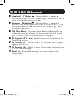
  Wavelength / VFL Button ( )

 – Press this button to change the 

wavelength setting in the power meter and light source screens. Hold it 
down to activate the Visual Fault Locator.

6

  Frequency / OSL Button ( )

 – Press this button to change the 

frequency when measuring the optical light source power loss or using 

the visual fault locator. Hold it down to initiate an optical light source 

power loss measurement.

7

  USB Micro-B Port

 – If the batteries you are using with the tester are 

rechargeable, you can recharge them by connecting this USB Micro-B 

port to the USB port on a computer or USB wall charger.

8

  FC Connector (OP)

 – Attach a cable to this connector when using the 

Power Meter function.

9

  FC Connector (SL)

 – Attach a cable to this connector when using the 

Light Source function.

10

  FC Connector (RL)

 – Attach a cable to this connector when performing 

a Visual Fault Locator test.

11

  Dust Cover

 – Protects FC connectors from, dust, dirt and other 

contaminants. 

15-11-089-9334DC-EN.indd   4

11/20/2015   2:11:04 PM

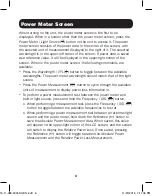
Summary of Contents for T020-001-PSF

Page 1: ...your product for quicker service and ultimate peace of mind You could also win an ISOBAR6ULTRA surge protector a 100 value www tripplite com warranty 1111 W 35th Street Chicago IL 60609 USA www trippl...

Page 2: ...in the cable featuring multiple frequency settings for continuous and flashing modes Light Source supports 1310 nm and 1550 nm wavelengths Power Meter supports 850 nm 1300 nm 1310 nm 1490 nm 1550 nm...

Page 3: ...power loss between an external light source and the power meter hold this button down to save the current power loss value When saved this value will appear in the upper right corner of the LCD screen...

Page 4: ...loss measurement 7 USB Micro B Port If the batteries you are using with the tester are rechargeable you can recharge them by connecting this USB Micro B port to the USB port on a computer or USB wall...

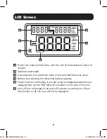
Page 5: ...Battery icon showing the remaining battery capacity 5 Power cord icon will display if you are using rechargeable batteries and charging them via the USB Micro B connector on the side of the unit 6 Au...

Page 6: ...should match that of the light source Press the Power Measurement button to cycle through the available units of measurement to display power loss information in To perform a power measurement test be...

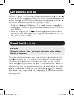
Page 7: ...uencies of 0 Hz 270 Hz 1000 Hz and 2000 Hz To initiate a visual fault locator test press and hold down the Wavelength VFL button The red laser will then be activated and sent through the connected cab...

Page 8: ...E POSSIBILITY OF SUCH DAMAGE Specifically TRIPP LITE is not liable for any costs such as lost profits or revenue loss of equipment loss of use of equipment loss of software loss of data costs of subst...

Reviews: