background image

Mount your equipment in either a 4-post or 2-post rack or rack enclosure (see next page for 2-
post mounting). The user must determine the fitness of hardware and procedures before
mounting. If hardware and procedures are not suitable for your application, contact the
manufacturer of your rack or rack enclosure. The procedures described in this manual are for
common rack and rack enclosure types and may not be appropriate for all applications.

4-Post Mounting

All UPS models include hardware required to mount in a 4-post rack. Select models include an
adjustable rackmount shelf kit to provide additional support. 

If your UPS model does not

include an adjustable rackmount shelf kit, skip steps 1 and 2.

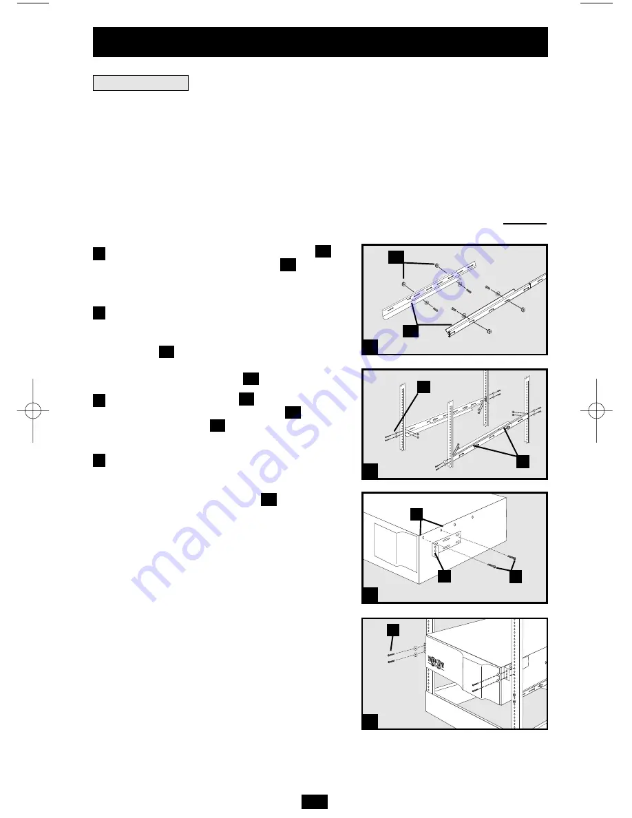
Connect the two segments of each shelf
using the included screws and nuts 

. Leave

the screws slightly loose so that the shelves
can be adjusted in the next step.

Adjust each shelf to fit your rack, then mount

them in the lowest available space of your
rack with the screws, nuts and washers
provided 

. Note that the support ledges

should face inward. Tighten the screws that
connect the shelf segments

.

Attach mounting ears 

to the front

mounting holes of your equipment 

using

the screws provided 

. The ears should face

forward.

Using an assistant if necessary, lift your
equipment and slide it onto the mounting
shelves. Attach your equipment to the rack by
using the appropriate hardware

through its

mounting ears and into the rack rails.

G

F

E

D

B

C

B

A

Rack Mounting

3

Installation

A

B

C

B

E

D

F

G

1

2

3

4

1

2

3

4

200507084 93-2474 SMARTONLINE HT OM.qxd  10/20/2005  11:11 AM  Page 3

Summary of Contents for Audio/Video On-Line UPS System

Page 1: ...ce 14 Audio Video True On Line UPS Systems Intelligent True On Line Operation Pure Sine Wave Output Zero Transfer Time 1000VA 2200VA Capacities Extended Run Options Warranty Registration 14 Copyright...

Page 2: ...he other end of this cord The UPS itself must be directly connected to a properly grounded wall outlet The total number of components connected should not exceed the UPS capacity This will overload yo...

Page 3: ...justable rackmount shelf kit skip steps 1 and 2 Connect the two segments of each shelf using the included screws and nuts Leave the screws slightly loose so that the shelves can be adjusted in the nex...

Page 4: ...r position with optional base stands sold separately by Tripp Lite Model 2 9USTAND When mounting the UPS on adjustable base stands make sure that the control panel is toward the top The control panel...

Page 5: ...hould not exceed UPS capacity This will overload your UPS system You will also overload your UPS if you connect household appliances to the UPS s outlets Turn your UPS ON Press the ON TEST Button Hold...

Page 6: ...e to a user supplied normally closed or normally open switch according to the circuit diagram see The EPO port is not a phone line surge suppressor do not connect a phone line to this port External Ba...

Page 7: ...The UPS will continue charging and the fan will continue to cool internal components even after you turn the UPS receptacles off To turn the UPS OFF completely including the charger disconnect the UPS...

Page 8: ...ndicate that the set of four dual function LEDs is displaying the load level of your UPS BATT ACTIVE METER LED This green light will illuminate when your UPS is operating from battery power to indicat...

Page 9: ...Lite Battery Packs for additional runtime Contact Tripp Lite Customer Support at 773 869 1234 for the appropriate Tripp Lite battery pack to connect Refer to instructions available with the Battery P...

Page 10: ...r RS 232 These ports connect your UPS to any Media Center PC or home automation system Use with Tripp Lite s PowerAlert Software and included cables to enable your Media Center PC home automation syst...

Page 11: ...the UPS output On FAULT Check the utility line for wiring problems Condition Wiring Fault such as reversed line and neutral or a missing ground On FAULT 100 Restart the UPS If the problem persists Con...

Page 12: ...High Output Voltage and Abnormal Input On FAULT Restart the UPS If the problem persists Flashing LINE 50 contact Tripp Lite for repairs Condition No Output due to Low Output Voltage and Abnormal Inpu...

Page 13: ...or hot swap replacement i e leaving the UPS in ON mode but some qualified service personnel may wish to put the UPS in the OFF mode and disconnect equipment before proceeding Procedure Remove Front Pa...

Page 14: ...s Only If your Modem Fax Protection causes harm to the telephone network the telephone company may temporarily discontinue your service If possible they will notify you in advance If advance notice is...

Page 15: ...15...

Page 16: ...1111 W 35th Street Chicago IL 60609 USA Customer Support 773 869 1234 www tripplite com 200507084 93 2474...

Reviews: