background image


15.


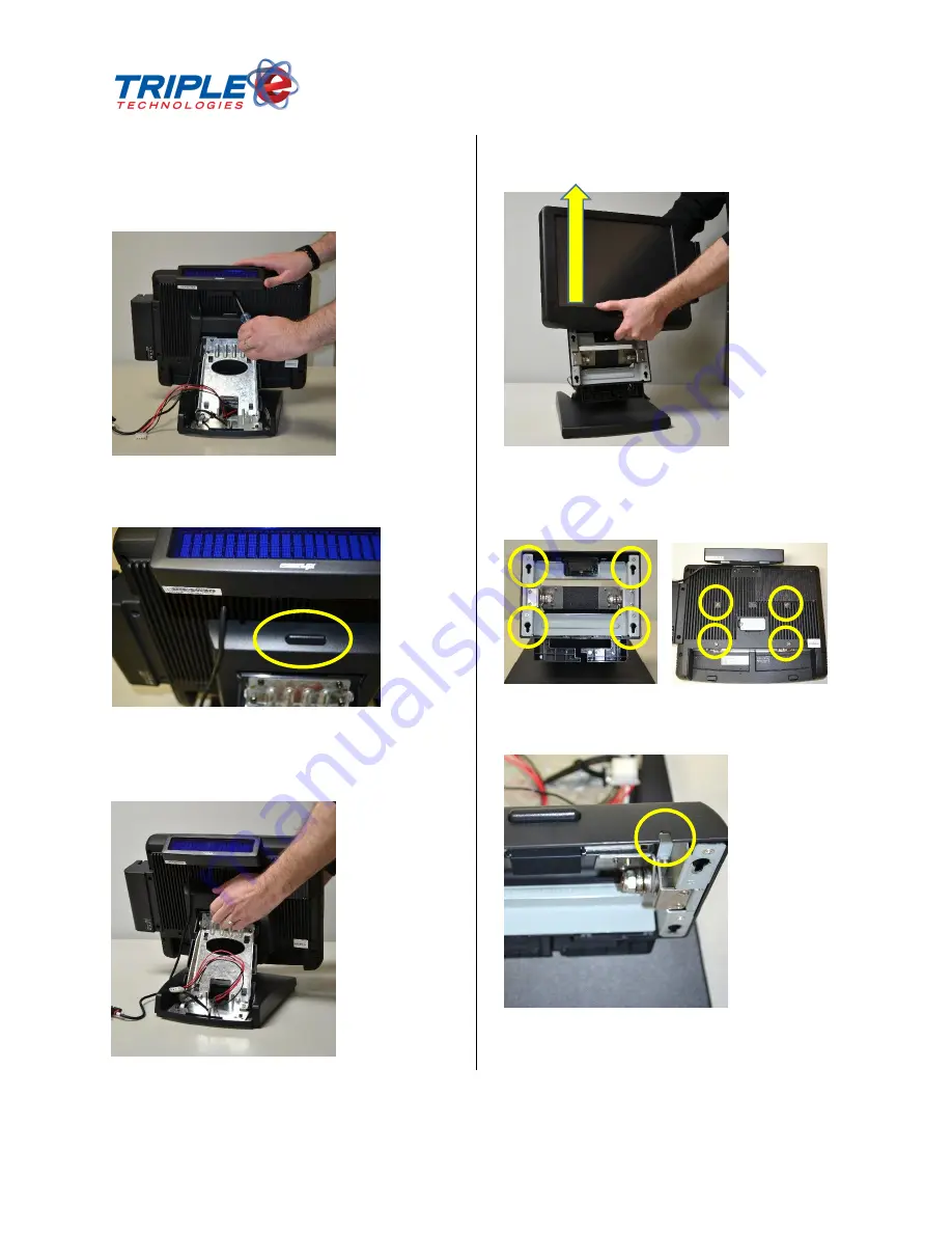
In this example, an optional customer 
display will be connected to ‘COM1’. The 
device is then mounted on the rear of the 
touchscreen with two screws. 


16.


Locate the touchscreen release button on 
the top rear of of the base. 


17.


Position one hand underneath the 
touchscreen. Press the release button with 
your other hand. 


18.


Lift the touchscreen up and away from the 
base. 


19.


Note the touchscreen is connected to the 
base unit by four pins that key into 
corresponding slots on the base unit. 


20.


Locate the customer display cable notch on 
the top of the base unit. 


Summary of Contents for POSIFLEX KS7215

Page 1: ...Copyright 2013 Triple E Technologies All rights reserved POSIFLEX USER INSTALLATION GUIDE...

Page 2: ...uct includes a lithium battery Always follow local environmental rules and regulations pertaining to the disposal of used batteries Always replace the battery only with a battery of the same type NOTE...

Page 3: ...in operating the opening mechanism and to monitor the drawer open status The connector cable for the Cash Drawer has a 6 pole plug at one end and an 8 pole plug at the other The 8 pole plug should be...

Page 4: ...all an optional card reader locate the accessory panel on the right hand side of the touchscreen 2 Remove the two screws that attach the panel to the touchscreen 3 Remove the panel The connector for t...

Page 5: ...on the card reader 6 Attach the card reader to the touchscreen with the same two screws previously removed 7 Locate the cable cover at the rear of the touchscreen base 8 Remove the cover by gently pr...

Page 6: ...bottom of the touchscreen 12 Locate the two locking tabs for the port cover Gently press down on these tabs and slide the cover away from the touchscreen 13 You should now be looking at the accessory...

Page 7: ...elease button on the top rear of of the base 17 Position one hand underneath the touchscreen Press the release button with your other hand 18 Lift the touchscreen up and away from the base 19 Note the...

Page 8: ...e You will hear a click when the unit is fully seated 23 Make sure the customer display cable is properly routed through the notch and all four pins are properly seated in their corresponding slots on...

Page 9: ...nect all USB devices such as a keyboard mouse signature capture device etc to the USB ports 29 Insert the network cable into the LAN port 30 Connect the cash drawer cable to the CR port 31 Connect the...

Page 10: ...een back into an upright position 35 At the rear of the touchscreen gather all of the cables into the lower left hand corner of the base except the customer display cable 36 Press the cable cover back...

Page 11: ...left hand side of the touchscreen Press in the center of the panel to open 38 Locate the power button and press it This will power on the touchscreen 39 Contact Triple E Technologies to complete the...

Reviews: