Operation
Determine Phase Rotation Direction
1. Connect the supplied color-
coded test leads to the meter’s test lead input jacks at the top of
the meter.
2. Connect the test probes to the three mains phases for the system under test.
3. Press and Hold the ON button to turn the meter on.
4. L1, L2, and L3 indicators will illuminate for each phase connected, respectively.
5. The clockwise and counter-
clockwise arrows with the left/right ‘L’ or ‘R’ icons display the
phase rotation direction (phase sequence) of mains as connected.
6. To understand the status of a test, based on the condition of the
meter’s front panel LEDs, refer to
the table printed on the meter:
Note
: The rotational indicator LEDs illuminate even if one of the test probes is connected to a
neutral or ground conductor instead of one of the mains phases.
Check Motor Turn Direction (contact method)
1. Connect the supplied color-
coded test leads to the meter’s test lead input jacks at the top of
the meter.
2. Connect the test (alligator) probes to the three motor connections (L1 to U, L2 to V, and L3
to W).
3. Press and Hold the ON button. The green ON indicator shows that the instrument is ready
for testing.
4. Turn the motor shaft continuously in a clock-wise rotation.
*Note: you must rotate the shaft with enough speed to generate a voltage that can be detected.*
5. The clockwise and counter-clockwise arrows with the left/right
‘L’ or ‘R’ icons display
the orientation of the motor.
Check Motor Turn Direction (non-contact method)
1. Disconnect the test leads from the meter and from any other devices under test.
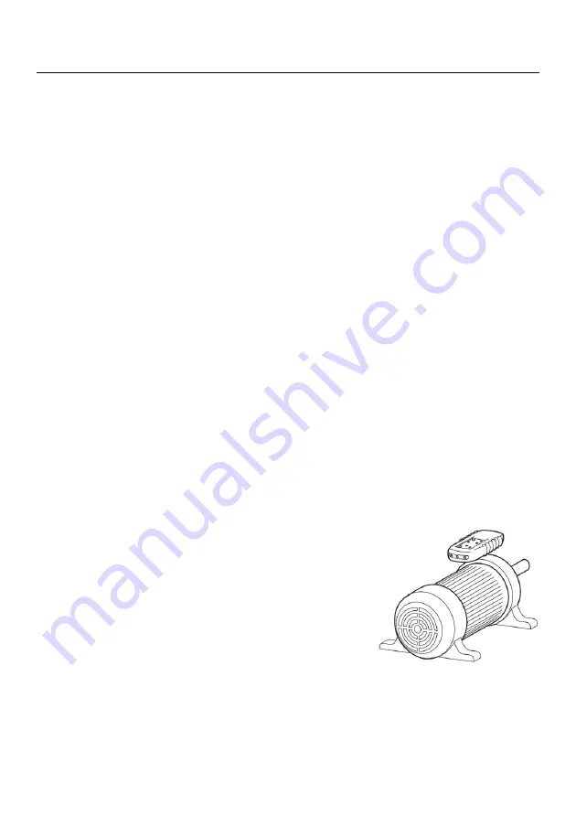
2. Hold the meter close (one inch or closer) to the motor,
parallel to the length of the motor shaft.
3. The bottom of the meter should face the drive shaft and the
back of the meter should be flush with the motor (refer to
diagram at right).
Note: There is an orientation symbol on the meter to assist.
4. Press and Hold the ON button. The green ON indicator
shows that the instrument is ready for testing.
5. The orientation of the motor is represented by the clockwise
and counter-
clockwise arrows with the left/right ‘L’ or ‘R’
icons display. Face the rear of the motor (meter will appear upside down) when reading
the status of the display LEDs.
Note: The meter will not operate with motors controlled by frequency converters (VFDs).
Magnetic Field Detection
1. Hold the meter in the area under test
.
Press and hold ON button.
2. A magnetic field is present if either the clockwise or the counter-clockwise LED illuminates.


