Herrmidicool
I n s t a l l a t i o n , O p e r a t i o n & M a i n t e n a n c e M a n u a l
5
www.trioniaq.com
NOTE:
Inlet water pressure must be in range of 50-100 psig. Consult
the factory if you are outside this range.
Supply Power
1. Supply power of 120 VAC, 5 amps is required.
2. Field wiring of the main power supply is connected directly
to the line power-filter in the control cabinet. A ground lug is
provided for the ground wire.
3. Install external overcurrent protection and provide wiring
in accordance with the NEC, state and local codes.
4. Power supply must be “clean;” free of spikes, surges and
sags; +10%, -15% of nominal. Ground should be true earth
ground.
V. CONTROLS
Controls may be supplied by the factory or others. The following
information applies to all controls factory supplied or furnished by
others. All external electrical control circuits are to be connected
to the unit using the terminal strip located in the electrical
compartment. Field wiring from humidistat to humidifier and
between safety devices, such as high limit humidistat and air
proving switches, should be 18 AWG stranded or 20 AWG solid
wire. Wall devices should be mounted at a height similar to
that of a typical thermostat and should be located in an area
that will provide good representation of the overall space being
humidified. Do not mount wall devices directly in the air stream
of a supply grille or room distribution unit.
Duct control devices should be mounted in a location where
the humidity and temperature are uniform, usually the return
duct.
Duct high limit devices should be mounted downstream of the
evaporative surface far enough that under normal conditions
in the air stream, the water has been completely evaporated,
typically 10 ft. The device should be located such that it can
sense humidified air as it approaches saturation. Do not
mount in dead air spaces such as inside of comers.
Air proving devices should be mounted so that they sense
airflow (or the absence of it). Wire the device so that it closes
when airflow is present and will open when there is no airflow.
The purpose of the device is to prove that airflow is present
before mist is distributed into the duct.
Your application specific wiring diagram, included with this
package will detail exact filed wiring connection points for
your unit.
Control Circuit Connections
On/Off (OPTIONAL – Limited Application)
1. Control Input - Unit will operate with any two-position
device. Demand for humidity will close the contact.
2. Limit Input - Unit will operate with any two-position device.
The humidistat contact will open on humidity rise.
VI. CONTROL BOARD OPERATION
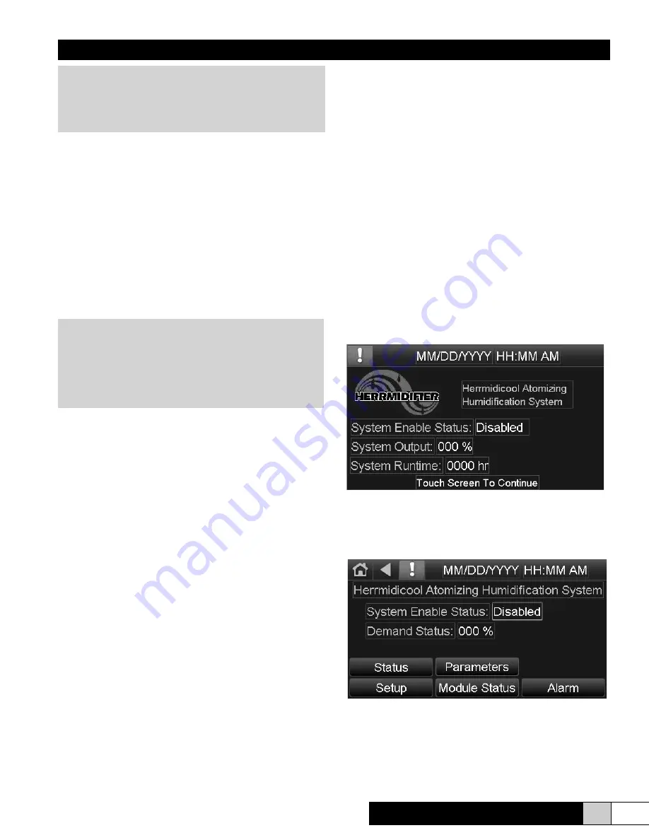
The Herrmidicool system is equipped with a native BACnet
controller. When power is applied to the system, the display
turns on and displays the STANDBY screen (shown below).
The STANDBY screen displays System Enable Staus
(enabled or disabled), the System Output, and the cumulative
hours of runtime. The number indicated represents the total
number of hours that the system solenoid valves have been
energized and spraying water for humidification.
Touching the screen anywhere will take you to the HOME
screen (shown below).
The HOME screen is a gateway to other screens. The
system may be Enabled or Disabled by touching the box next
to System Enable Status. A window will pop-up and the user
can make their selection. Upon being enabled, the system
will respond to increases or decreases in the Demand Input
WARNING
Do not mount any controls inside the unit or tap power
from any location in the unit, except as stated in these
instructions. Do not place objects near the cabinet.
Do not attach to dry wall without studs.
CAUTION
Any minerals that are in the water will be injected into
the airstream. Your application/process may require
some means of air or water filtration to complete a
successful application. Consult the factory if you
should have any questions. Softening the water
only increases the TDS level.


