


Version 3.2
Page: 44
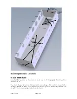
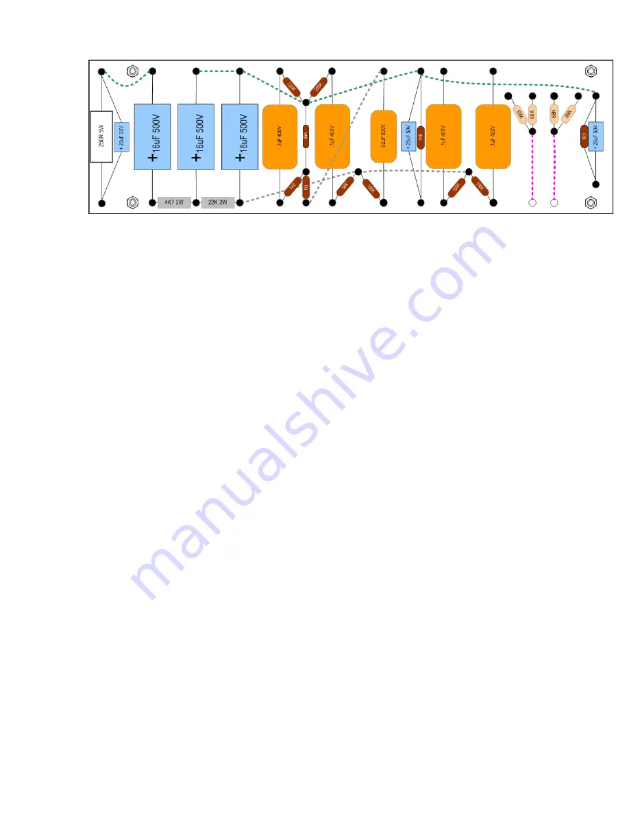
Install the components on the board by following the layout from left to right.
Start with the bigger parts on the power supply side of the board. Then, work your way over to
the signal components. Make all of your connections as neatly as possible. At each eyelet,
mount and solder ALL of the components including the flying leads that belong in each eyelet
and solder once.
Crimp all wires tightly at the connection point before soldering. Remember, if your solder
joints are not bright and shiny; do them over until they shine like jewels. Double check all of
your connections for shorts against adjoining components or terminal posts.
Flying leads
are also installed at this time. Cut connecting wires in various colors and about
6” (rear)
-
8” (front) long each.
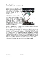
Following the layout, install the connecting wires to the bottom
of the board leaving plenty of extra length, wire is not expensive and it'll save aggravation later
Start with the 250 ohm 5Watt / 25uF capacitor pair. Note: Make sure the cathode pair are
separated slightly as this resistor emits some heat. Install flying leads and solder in place
Move on to the 3 - 16uF 500V filter capacitors and power supply resistors.
Continue with the remaining parts, following the layout provided.
Note: For multiple component leads that must fit into one eyelet or eyelet, insert them first
and solder once when they are all in place. Bend each component lead at 90 degrees so that it
fits into the eyelet squarely and neatly. Solder each eyelet once all component leads that
connect to it, jumpers and flying leads are in place.
Tip: Circle each "eyelet" on a printed copy of the layout as you complete each connection to
that point to track progress and confirm that all parts are in the correct orientation and
position. It's well worth the time to re-check the eyelet board layout before installing it in the
chassis.
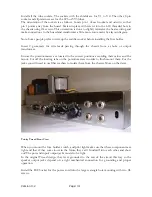
The old style 'point to point' wired eyelet board used in this project is mounted on stand-offs
to the chassis. This is an improvement over the original design which allowed the board to
‘float’.
For convenience, the holes for the #6 standoff bolts are threaded in the chassis so screw the
bolts into place from the outside then put the standoffs on these. Install the eyelet board
Summary of Contents for Trinity Tweed Amp
Page 2: ...Version 3 2 Page 2 ...
Page 16: ......
Page 20: ...Version 3 2 Page 20 Input Jack Theory from 18watt com ...
Page 25: ...Version 3 2 Page 25 ...
Page 49: ...Version 3 2 Page 49 ...
Page 65: ...Version 3 2 Page 65 HEYBOER OT for TWEED 6L6GT CONVERSION ...
Page 66: ...Version 3 2 Page 66 ...
Page 75: ...Version 3 2 Page 75 ...
Page 76: ...Version 3 2 Page 76 ...
Page 77: ...Version 3 2 Page 77 Trinity Amps Schematics and Layouts ...