Trinamic TMCM-160 Manual Download Page 11

TMCM-160 Manual (V1.11 / August 8th, 2007) 


11 


Copyright © 2006, TRINAMIC Motion Control GmbH & Co. KG 


5.8  Parameterizing the PID velocity regulator 

 
The motion control commands (TMCL_ROL, TMCM_ROR, TMCL_MVP) use a PID regulator for velocity 
control. The PID regulator has to be parameterized with respect to a given motor in a given 
application. The default parameter set of the PID regulator covers a range of motors suitable for the 
TMCM-160 module, and typically works stable up to 15000 rpm maximum motor velocity. However, for 
slower motors, the response time with this parameter set may become quite slow.  
The PID regulator uses four basic parameters: The P, I and D values, as well as a timing control value. 
The timing control value (PID regulation loop delay) determines, how often the PID regulator is 
evoked. It is given in multiple of 10ms:  
 

t

PIDDELAY

 = x

PIDRLD

 * 10ms 

x

PIDRLD

 is the PID regulation loop delay parameter, t

PIDDELAY

 is the resulting delay between two PID 

calculations 

 
The PID parameters are divisors, e.g. use a higher value, to get less influence from the parameter. To 
parameterize for a given motor, first modify the P parameter, starting from a high value and going to 
a lower value, until fastest response with minimum oscillation is given.  
After that, do the same for the I parameter. Now, modify the D parameter in the same way. It will 
damp part of the oscillations of the other parameters, too. 
 
As a thumb-rule, you can set the P-parameter to a starting value, such that: 
P-param = (Maximum actual RPM of the motor at 100% PWM) * 0.15 
 
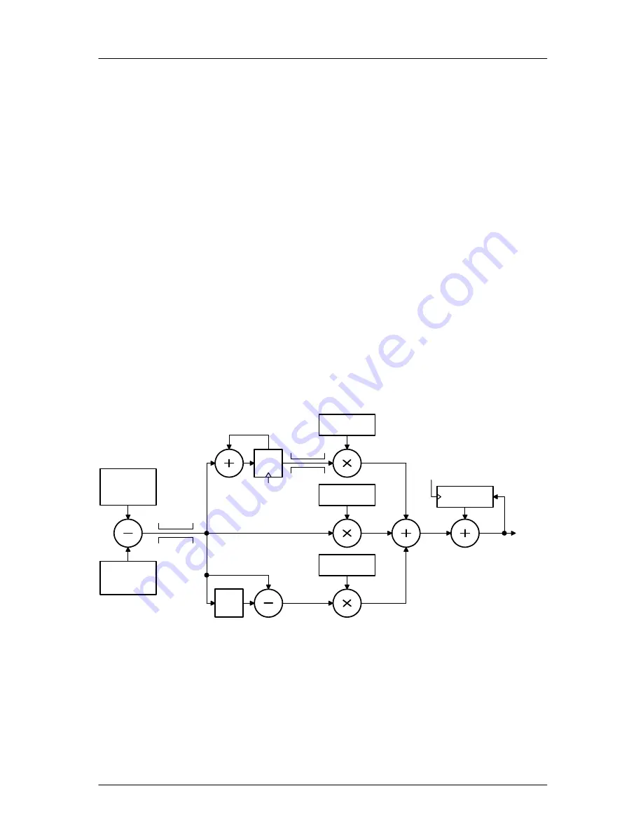
The module uses the internally calculated velocity value (1/4 of electrical RPM value) as input into the 
PID regulator (see schematic).  

actual RPM

(1/4 electrical

RPM)

target RPM

(1/4 electrical

RPM)

Clip

4095

32 / P-param

sum

Clip

32767

32 / I-param

last

32 / D-param

actual PWM

0-1023

new PWM

CLK: 100Hz /
PIDloopdelay

CLK: 100Hz /
PIDloopdelay


Figure 5.1: PID velocity regulator parameters 

 
Default values: 
P-param = 2400 
I-Param = 150 
D-Param = 600 
x

PIDRLD

 = 2 

Summary of Contents for TMCM-160

Page 1: ...60 Hardware BLDC motor controller driver module 5A 36V with RS232 RS485 and analog interface V1 11 August 8th 2007 Trinamic Motion Control GmbH Co KG Sternstra e 67 D 20357 Hamburg Germany www trinami...

Page 2: ...le motor current limit 10 5 8 Parameterizing the PID velocity regulator 11 5 9 Parameterizing the positioning algorithm 12 5 10 Restoring factory default settings 12 6 Revision History 13 6 1 Document...

Page 3: ...ions with automatic ramp generation Remote controlled RS232 or RS485 or stand alone operation 0 10V signal Plug On module or panel mount operation Very compact multi axis drives integrate several modu...

Page 4: ...uipment intended to support or sustain life and whose failure to perform when properly used in accordance with instructions provided can be reasonably expected to result in personal injury or death TR...

Page 5: ...7 9 8 10 11 13 12 14 15 17 16 18 19 21 20 22 23 25 24 26 U U V V W W VS VS GND GND GND 5V H3 H2 H1 GND GND GND VS VS W W V V U U Figure 3 1 Pinning CAUTION Since the two connectors of the TMCM 160 ar...

Page 6: ...FF Emergency stop Tie this pin to GND to stop the motor same as Motor Off switch on PCB The motor can be restarted via the interface or by cycling the power supply 8 LED_TEMP 5V TTL output Toggling wi...

Page 7: ...uded since these are just for evaluation purpose Figure 3 2 Dimensions 3 3 Connectors Hall sensor JST1 5mm type S5B ZR SM2 TF only on EvalBoard Board Plug on connectors 2 54 mm two row Header 3 4 Appl...

Page 8: ...0 3 VCC 0 3 V VO Logic output current on digital outputs 5V CMOS output 10 mA VIA Analog input voltage 24 0 10 24 V fCHOP Chopper frequency 20 kHz Ex Exactness of voltage and current measurement 8 8 T...

Page 9: ...ntrol flag 1 Power on velocity v Table 5 1 Options for stand alone operation In all modes the motor torque is limit by the maximum current setting The polarity of the DIR pin can be inversed by the di...

Page 10: ...le the TMCM 160 calculates a reduced PWM value for the next chopper cycle New values are calculated 100 times a second The response time of the current regulation can be set using the parameter curren...

Page 11: ...on loop delay parameter tPIDDELAY is the resulting delay between two PID calculations The PID parameters are divisors e g use a higher value to get less influence from the parameter To parameterize fo...

Page 12: ...pplication 5 Set MVP_target_reached_distance to the value which gives a stop as near as possible to the target position velocity position target position set via MVP max_pos_speed min_pos_speed MVP_ta...

Page 13: ...d RS485 Tacho output Added baud rate switching Added RS485 interface Fixed current regulation bug GPIO1 provides for a hall sensor derived tacho signal Analog control input now uses 10 bit resolution...

Reviews: