


TMCM-035 Manual (V2.09 / February 27
th
, 2009)
12/18
Copyright © 2007-2009, TRINAMIC Motion Control GmbH & Co. KG
4.4
Current setting
The motor current setting can be selected by connecting the RSA and RSB pins to GND as shown in
the following table.
Note: In step-/direction mode the motor is without current until the first step impulse is given. The
same applies after a disable/enable cycle.
Caution: Never leave both, RSA/B1 and RSA/B2 pins, open!
peak coil current
RMS current
(microstep operation)
RSA1, RSB1
RSA2, RSB2
1.5 A
1 A
GND
open
3.4 A
2.5 A
open
GND
5.0 A
3.5 A
GND
GND
variable
peak current / 1.41
(external resistor from RSA/RSB to GND)
Table 4.7: Current setting
4.4.1
Fine current adjustment in SPI mode:
In SPI mode, the current values set via the sense resistors can be modified using the analog inputs
INA and INB. In this case the ANN input (pin 25) must be pulled low. The INA and INB inputs
supporting a voltage range of 0 to 3V can be used. Use a simple voltage divider on the 5V supply to
accomplish this, e.g. a 10K Potentiometer. A value of 2V corresponds to the currents given in the
table, i.e.
Current set value = (Value from Table 4.7) * (INA/INB-Voltage) / 2V
Please be careful with values of INA/INB > 2V since the maximum current of the module can be
exceeded (150% at 3V).
In 64 microstep mode the current adjustment via the analog inputs is limited. The voltage on INA and
INB should not exceed the range from 1.5 to 2.5 V in your application.
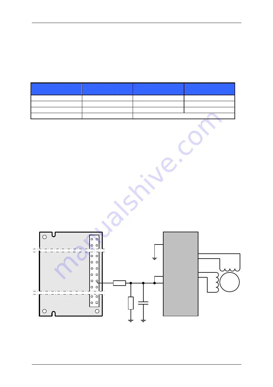
Following exemplary R/C filter gives an analog voltage range of about 0 to 2.1V.
Pin 2
Pin 30
Pin 32
Pin 34
Pin 36
Pin 38
Pin 40
Pin 68
TMCM-301
31
33
35
M
GND: Pin 2, 4, 6, 8
5V : Pin 1, 3
TMC249 /
TMCM-035
INB
OUTA1
OUTA2
OUTB1
OUTB2
PWM
47k
47k
470nF
INA
GND
GND
ANN
Figure 4.5: Application example for a TMCM-035 and TMCM-301 with analog current control


