


TMCM-035 Manual (V2.09 / February 27
th
, 2009)
11/18
Copyright © 2007-2009, TRINAMIC Motion Control GmbH & Co. KG
4.3.3
Step / Direction
To use the Step / Direction interface connect the inputs as follows:
Signal name Pin number Connection
SPE
19
high (+5V, can be left open alternatively)
SDEN
22
high (+5V, can be left open alternatively) , step / direction enable
STEP16
24
high for 16, low for 8 microsteps (STEP64EN is high)
high for 64, low for 32 microsteps (STEP64EN is low)
STEP64EN
27
high (can be left open) for 8/16 microsteps, low for 32/64 microsteps
available since version 2.0
USEMD
26
Set high (or leave open) to use mixed decay (recommended for most
applications), or low to use slow decay.
Step In
18
Connect your step signal here. The rising edge of the signal is a step
pulse.
Direction In
20
Connect your direction signal here.
ANN
25
Do not connect!
Table 4.5: Step / Direction interface connections
Note: Pins 12, 13, 14, 16 and 25 must not be connected in this mode!
The Step / Direction interface can also be used to connect the TMCM-035 module to a TMCM-100
module (however it results in a higher microstep resolution, if the analogue interface is used with the
TMCM-100). Here is how to do it:
TMCM-035 pin number
TMCM-100 pin number
Signal name (TMCM-035)
1, 3
1, 3
+5V
2, 4, 6, 8, 10
2, 4, 6, 8, 10
GND
11
--
Enable, connect to GND
18
20
STEP
20
19
DIR
Table 4.6: Connecting a TMCM-035 to a TMCM-100 (step / direction)
In step / direction mode the LED shows the status of the module:
The LED is on when the motor is enabled and the supply voltage is high enough.
The LED is off when the motor is disabled due to pin 11 (Enable) set high or supply voltage to
low.
The LED flashes when there is an error (please refer to chapter 4.3.2 for more information).
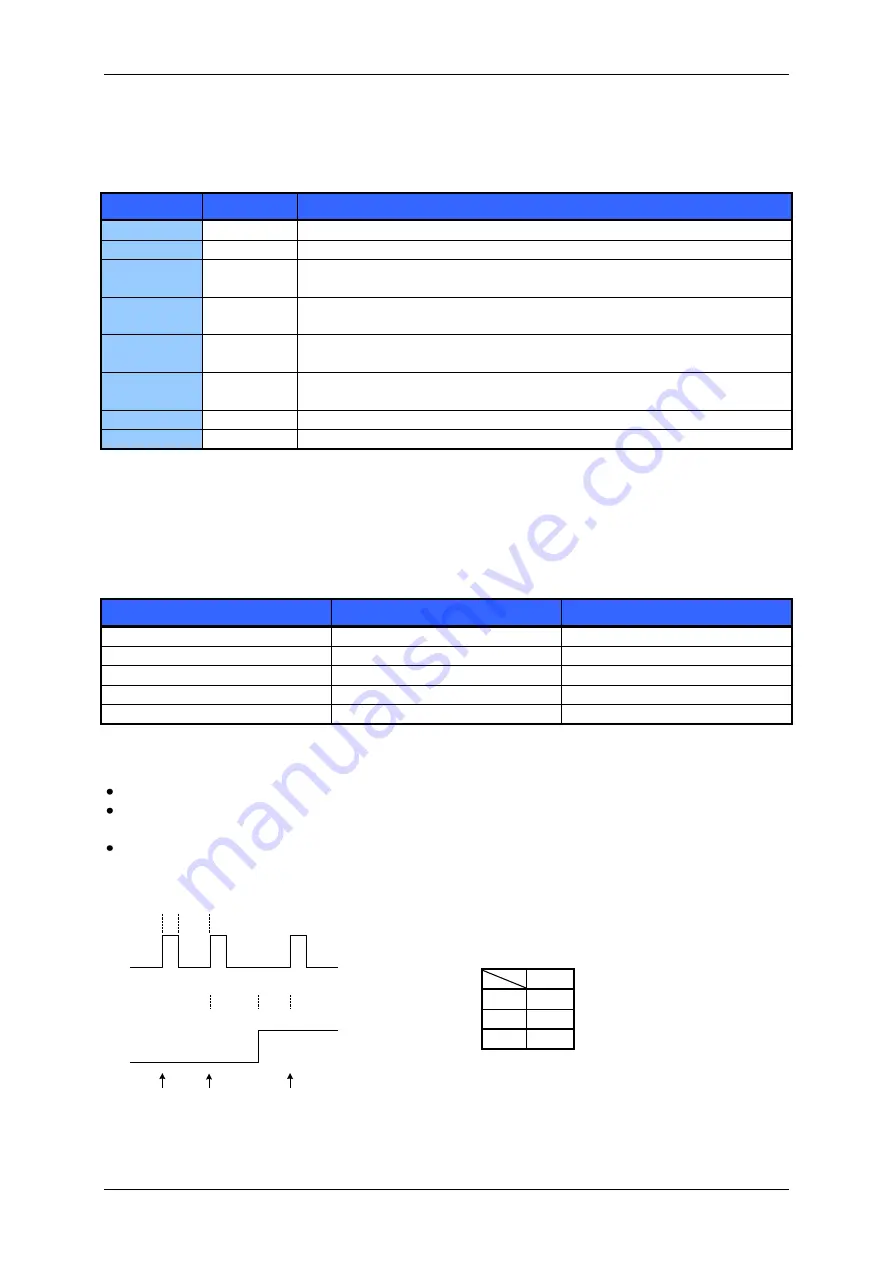
Step-Direction signal timing:
Step pulse
Direction
th
tl
t
S2D
t
D2S
2 steps CW
CCW step
step
Figure 4.4: Step / Direction signal timing
Min
T
S2D
2 µs
T
D2S
0 µs
th
0.1µs


