TMC389-EVAL MANUAL (V. 1.10 / 2011-Mar-01)
3
Copyright © 2010 TRINAMIC Motion Control GmbH & Co. KG
3 General Description
+V
M
HS
LS
TMC389
BM
RS
STEP
DIR
CSN
SCK
SDO
SDI
ENABLE
SG_TST
CLK
5VOUT
VS
220n
VCC_IO
470n
VHS
Microcontroller
CSN
SCK
SDI
SDO
CLK OUT
CLK_ARM
CLK
GND
S
D
G
1K
+V
CC
0R15
Soldering Jumper
ENABLE
STEP
(TRISTATE)
DIR
(TRISTATE)
D
IR
S
T
E
P
+V
CC
G
N
D
STEP/DIR input
M
o
to
r
c
o
n
n
e
c
to
r
+V
CC
5V
3V3
3V3
I/O voltage
jumper
CLK source
jumper
3.3V regulator
G
N
D
+
V
M
Supply
+
V
M
3
V
3
RS232
USB
TMC389-EVAL
3phase
stepper
N
S
U
V
W
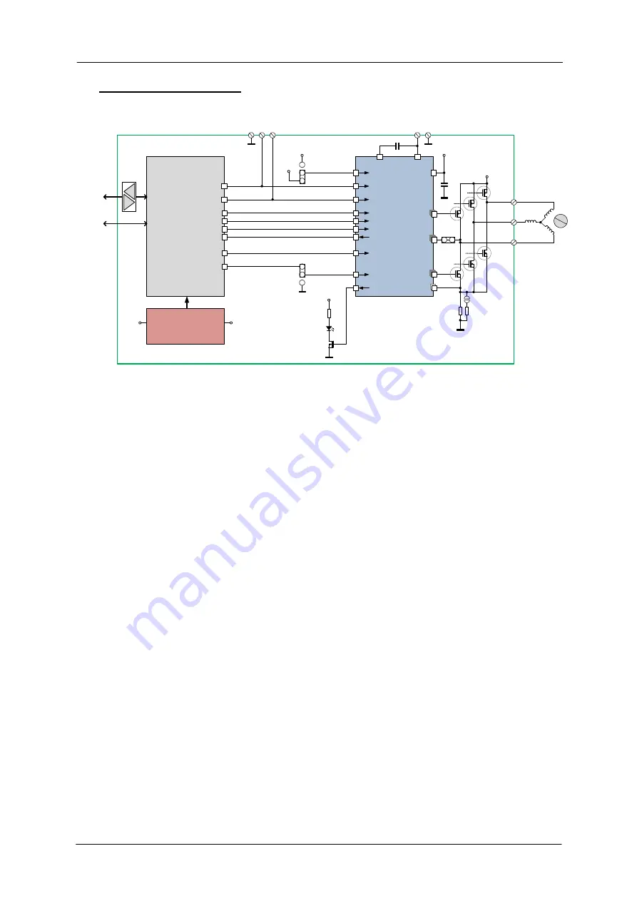
figure 1: application block diagram as realized on TMC389-EVAL
The TMC389-EVAL board features the TMC389 plus a microcontroller, which realizes an interface to a
PC.
3.1 Power driver stage
The power MOSFETs on resistance mainly influences the current and voltage capability of the board.
Therefore, a choice of different MOSFETs can be soldered to the board.
Component selection:
The TMC389 driver has powerful 40V MOSFETs FDD8424H for motor currents up to 6A peak.
With these MOSFETs, the supply voltage is limited to 40V.
The MOSFETs can be exchanged against complementary N&P channel SO8 types, e.g. 60V type
SI4559ADY (SO8). These will allow a motor current of max. 3A peak.
Small 60V MOSFETs SI3458BDV and SI3459BDV are also possible for up to 2A peak.


