


PD-013-42 / TMCM-110-42 Manual (V1.24/2011-NOV-25)
12
Copyright © 2011, TRINAMIC Motion Control GmbH & Co. KG
Examples:
1.
Set chopper mode to SPI Mode:
AM 0
ENTER
2.
Read out the actual mode:
Am
ENTER
3.
Change Microstep resolution ¼ of max. resolution:
AZ 2
ENTER
Example for test move:
˗
Different accelerations and velocities
˗
AA 500, AV 50000, AV -50000
try other AA 0…8000, AV 0…400000
˗
Max. current – test of torque
˗
AA 500, AV 50000, AC 200
test torque manually
AC 20
test torque
˗
Read and set position
˗
AV 0, AR, AA 500, AV 50000, AR, AP 0, AR
7.2.1.1
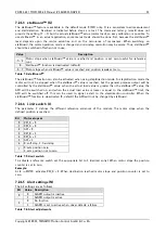
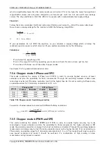
Motor current (C) setting with RS485 command
The motor current can be set by the user. Therefore use the RS485 command
AC
in addition with a percent
value. For calculating the actual setting, use the 100% values as shown in the table. Internally the current is
regulated by two independent parameters for the best module/motor performance possible.
For chopper mode 2, the maximum setting is about 75% to 90%. At higher settings the microstep behavior
of the motor may become harsh. The actual maximum depends on the actual motor. This is a precaution to
avoid the motor coil current raising above the 100% setting at any time. Not all currents can be
continuously driven at all supply voltages and cooling circumstances. Please take care of the motor current
limitations.
AC
I
COIL,PP
I
COIL,RMS
% to max. I
COIL
100
1.50A
1.06A
100% *)
80
1.20A
0.85A
75%
66
1.00A
0.71A
66%
50
0.75A
0.53A
50%
33
0.50A
0.35A
33%
20
0.30A
0.21A
25%
0
0A
0.00A
0%
Table 7.2: Motor current examples
*) not possible for chopper mode 2
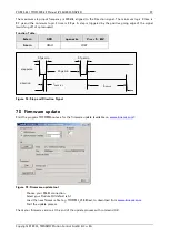
7.2.1.2
Failure readout (E)
The TMCM-013 provides a full driver failure analyses in SPI mode (8 Bit).
The returned bit assignments are as follows:
Bit
Name
Function
Remark
7
OT
overtemperature
“1” = driver chip off due to overtemperature
6
OTPW
temperature prewarning
“1” = driver chip prewarning temperature exceeded
5
UV
driver undervoltage
“1” = undervoltage on VS
4
OCHS
overcurrent high side
3 PWM cycles with overcurrent within 63 PWM cycles
3
OLB
open load bridge B
Open load detection can occur at fast motion also.
2
OLA
open load bridge A
Open load detection can occur at fast motion also.
1
OCB
overcurrent bridge B low side Short circuit detected. Please check motor wiring.
0
OCA
overcurrent bridge A low side Short circuit detected. Please check motor wiring.
Table 7.3: Failure readout in SPI mode
In the other two modes the failure analysis consists of only one bit:
1: short circuit or overtemperature
0: no failure


