


PD-109-57 / TMCM-109-57 Manual (V1.10 / October 17th, 2007)
16
Copyright © 2006, TRINAMIC Motion Control GmbH & Co. KG
Extern
V
OPTON
GND
V
OPTOFF
Intern
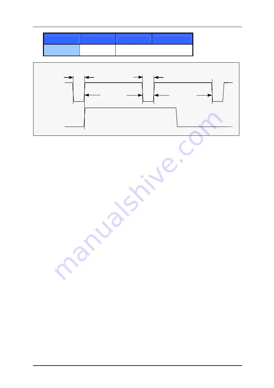
HIGH LOW
step pulse
direction
0.7µs min
2.0µs min
2.0µs min
0.7µs min
same minimum times as above
Figure 5.2: Step and Direction Signal
5.9 Reference
Switches
Two digital reference / stop switch inputs are provided (StopL= stop left and StopR = stop right). They
are used as an absolute position reference for homing and to set a hardware limit for the motion
range. The inputs have internal pullup resistors. Either opto-switches or mechanical switched with
normally closed contact can be used. The 5V output can be used as an supply for opto-switches.
5.10 StallGuard™ - Sensorless Motor Stall Detection
The integrated StallGuard™ feature gives a simple means to detect mechanical blocking of the motor.
This can be used for precise absolute referencing, when no reference switch is available. The load
value can be read using a TMCL command or the module can be programmed so that the motor will
be stopped automatically when it has been obstructed or the load has been too high. Just activate
StallGuard and then let the traveler run against a mechanical obstacle that is placed at the end of the
operation area. When the motor has stopped it is definitely at the end of its way, and this point can
be used as the reference position.
Please see the TMCL Reference and Programming Manual on how to activate the StallGuard feature.
The TMCL IDE also has some tools which let you try out and adjust the StallGuard function in an easy
way. This is also described in the TMCL Reference and Programming Manual.
Mixed decay should be switched off when StallGuard operational in order to get usable results.
5.11 Environment Temperature Considerations
As the power dissipation of the MOSFETs is very low, no heat sink or cooling fan is needed, unless
environment temperature is raised and the module continuously is operated at a high current.
When the output bridge temperature reaches a critical value, the output current is reduced by 20%. If
the temperature still rises higher, the outputs become switched off. The coils are automatically
switched on again when the temperature is within the limits again. An optional cooling fan can be
mounted to cope with higher environment temperatures, when problems are perceived. The 5V power
supply output can be used to operate a small fan.


