


BB-100 Manual (v 1.00 / April 5th, 2006)
8
Copyright © 2006, TRINAMIC Motion Control GmbH & Co. KG
4 Operational Ratings
The operational ratings show the intended / the characteristic range for the values and should be used
as design values. In no case shall the maximum values be exceeded.
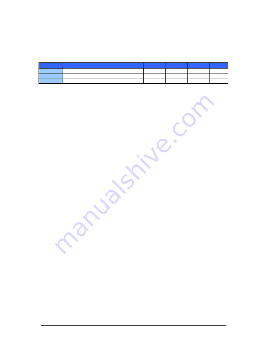
Symbol
Parameter
Min
Typ
Max
Unit
VS
Power supply voltage for operation
15
50
V
T
ENV2A5
Environment temperature at 2.5A RMS
-25
60
°C
T
ENV3A5
Environment temperature at 3.5A RMS
-25
40
°C
Table 4.1: Operational Ratings (pls. refer [TMCM-035] and [TMCM-100]
4.1 Motors
The TMCM-035 onboard the BB-100 operates a wide range of bipolar 2-phase stepper motors. Motors
with nominal currents above 5 amperes (peak) can be used, too. Please refer [TMCM-035] for details.
Low supply voltage limits can be disregarded because the drivers operate in current regulating mode.
The minimum coil resistance is not limited, even a short circuit does not lead to damage. High coil
resistance (e.g. above 10 ohms) might cause limited dynamical performance and/or reduced
maximum motor speed. A coil inductance in the range of 1 mH results in good current regulation with
low current ripple. Even inductance lower than 1 mH is allowed but the inductance of typical stepper
motors is above 1 mH.
5 Getting Started
The power supply has to be disconnected when plugging in a TMCM-035 or TMCM-100 module
into the BB-100. Do not connect or disconnect the motor while the unit is powered. Connecting
or disconnecting the motor while the unit is powered might damage it.
5.1 Power Supply and Motor Connection
The stepper motor must not connected or disconnected when it is powered, because this can
destroy the power stage of the TMCM-035 module due to high voltage generated by the
inductance of the coils of the stepper motor.
An unregulated supply voltage (V+) is sufficient for the BB-100, but it must not exceed the range from
15 to 50 Volts. Generally, high supply voltage (e.g. 24V, 40V) that is compatible with the stepper motor
should be preferred. A higher supply voltage results in a better dynamic behavior of a stepper motor.
The alternative supply voltage input marked with the diode symbol features a reverse current
protection for the power supply. Reverse currents might occur during fast deceleration at high
currents. A low end power supply might be damaged by reverse currents. This diode also features a
reverse polarity protection for the BB-100 with the TMCM-035 and TMCM-100. The integrated switch-
mode regulator provides the required 5V supply voltage for the modules


