Trillium SARASIN-RSBD 78 Series Installation, Operation & Maintenance Manual Download Page 16

7.5 OPTIONS 

7.5.1  REMOTE SENSE  

• Safety valve will respond to actual system pressure conditions. 
• Eliminates undesirable cycling due to excessive inlet pressure losses.
• Improves safety, under adverse operating conditions.  
 

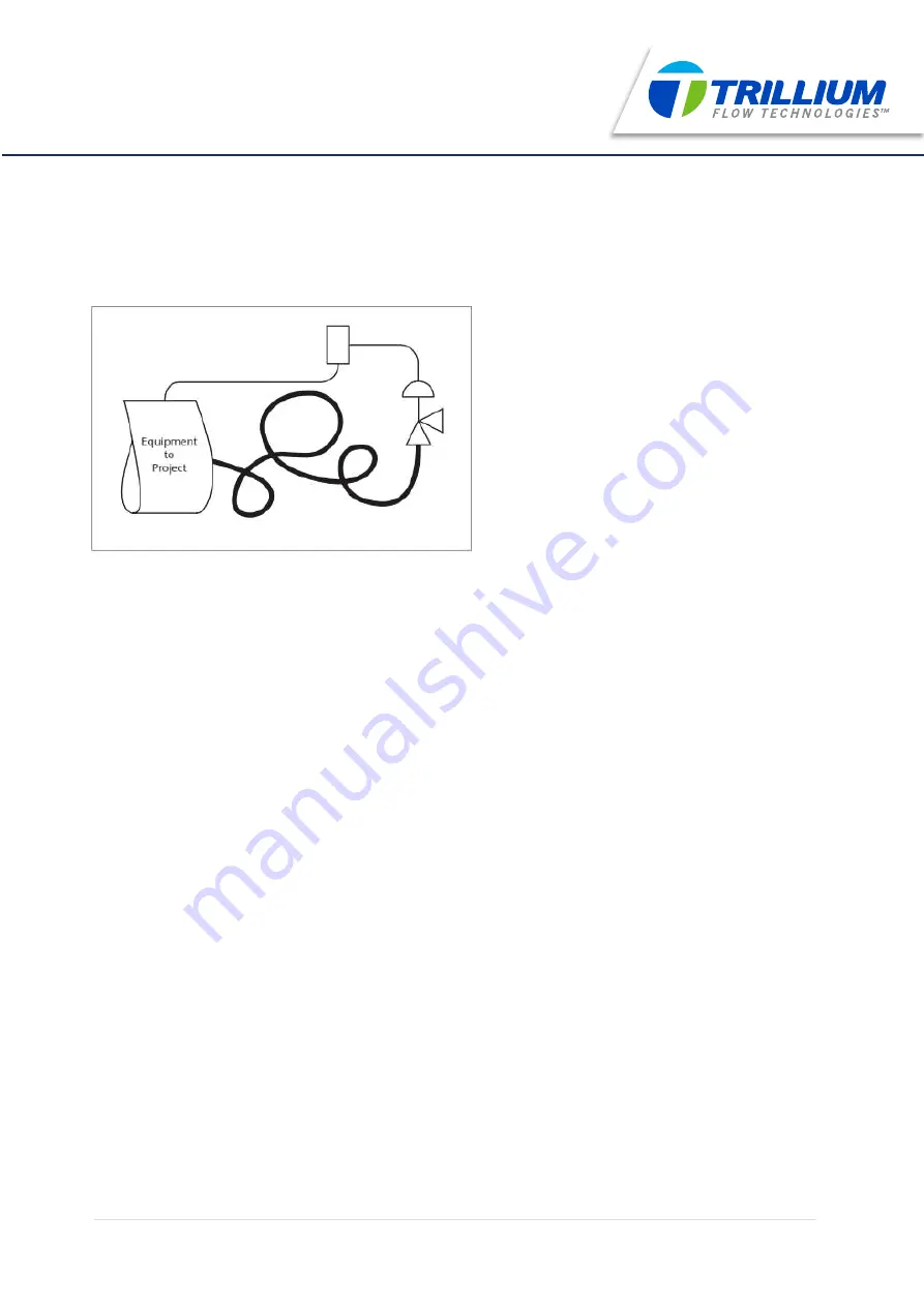
This optional feature permits the pilot to sense system pressure at a location that most accurately reflects the actual operating 
pressure of the protected system. 
 
A remote pressure sense connection eliminates the false system pressure indication that will occur during relieving conditions, due 
to pressure losses in the inlet piping to the safety valve. Most applicable codes recommend that the inlet piping system be designed 
for a maximum anticipated non-recoverable pressure loss of 3 percent. If this is not possible, the remote pressure sense connection 
should be specified. 
 
Please note that the addition of a remote pilot sense line allows the pilot to correctly sense system pressure and to keep the valve 
from rapid cycling or chattering. With remote sensing the piston type, pilot operated safety valves described in this catalogue will 
remain stable against the effects of high inlet pressure loss phenomena. However, relieving capacity will be proportionately reduced 
whenever there is inlet pressure loss to the safety valve.


15

|

www.trilliumflow.com


78 SERIE SAFETY RELIEF VALVE 

SARASIN-RSBD

Summary of Contents for SARASIN-RSBD 78 Series

Page 1: ...78 SERIES Installation Operation Maintenance Manual...

Page 2: ...NOMENCLATURES 10 7 INSTALLATION 12 7 1 GENERAL 12 7 2 INLET PIPING 12 7 3 OUTLET PIPING 13 7 4 INSTALLATION ON THE PROTECTED EQUIPMENT 13 7 5 OPTIONS 15 7 5 1 remote sense 15 7 5 2 field test connecti...

Page 3: ...ING CAUTION ATTENTION DANGER WARNING CAUTION ATTENTION DANGER Immediate danger which WILL cause serious personal injury or death WARNING Risk or dangerous practice which COULD cause serious personal i...

Page 4: ...s Pictograms are used to clearly advise of the potential dangers associated with the use of theproduct Whilst this document is intended to be informative it is important to understand that the safety...

Page 5: ...valve for disassembly ensure that there is no remaining pressure upstream the valve and that the valve is isolated from the system pressure Before performing each pop test on the safety valve ensure t...

Page 6: ...ed in order for Trillium Flow TechnologiesTM to inspect the product Trillium Flow TechnologiesTM cannot be held responsible for any incorrect sizing and selection of a valve if the original specificat...

Page 7: ...or nozzle or at which the lift becomes zero LIFT The actual travel of the disc away from closed position when a valve is relieving LEAK TEST PRESSURE Leak test pressure is the specified inlet static p...

Page 8: ...iesTM organisation 5 2 IDENTIFICATION PLATE The data shown on the identification plate figure 1 should be referenced with all requests for work or for the supply of spare parts The identification plat...

Page 9: ...an cause permanent deformation to the spring Below than 5 adjustment can cause the pilot not to open fully For more than 5 adjustment you must contact Trillium Flow TechnologiesTM Sarasin RSBDTM After...

Page 10: ...ons the ingress of sand dust or any other solid particles or foreign matter Wherever possible the valves should be stored in their original packaging Blanking plugs thread protectors and plastic cover...

Page 11: ...design in accordance with ASME B16 34 and API STD 526 spring loaded table ASME B PV Code section VIII div I design o 10 overpressure o Blowdown between 5 and 10 o Capacity certified gas steam and or w...

Page 12: ...sc B 35 Stud E 40 O Ring A 43 Seat O Ring A 46 Return Spring D 50 Nut D 56 Piston C 82 Retainer Washer A 83 Retainer Screw A FIGURE 2 Metal Metal Seated Configuration 01 02 06 08 07 09 10 11 40 43 46...

Page 13: ...on of the seating surfaces Such erosion develops quickly due to the high pressure The system should always be purged before safety valve is installed Prior to installation of the safety valves all pro...

Page 14: ...ENT The equipment nozzle on which the safety valve is to be connected must be designed to give direct flow There must be no obstruction between the equipment and the safety valve The pressure relief v...

Page 15: ...ighten alternatively until the required torque is reached This should be done in 3 or 4 steps Nominal tighten torque table p 28 NOTE Due to the relaxation of the gasket it should be checked it 24 to 4...

Page 16: ...safety valve Most applicable codes recommend that the inlet piping system be designed for a maximum anticipated non recoverable pressure loss of 3 percent If this is not possible the remote pressure s...

Page 17: ...are pressurized simulating an increased system pressure When set pressure is reached pop action pilots only the pilot will actuate This actuation pressure may then be compared with the nameplate valu...

Page 18: ...ermitting the introduction of outlet pressure into the dome of the main valve thereby holding the piston firmly onto the nozzle overcoming the effect of a reverse differential pressure across the safe...

Page 19: ...st effective responsive manner If the safety valve is exposed to hazardous weather conditions ingress of dirt or other foreign matter or any extremes of temperature conditions please ensure that The v...

Page 20: ...maintenance operation the system upon which the pressure relief valve is installed must not be pressurised 19 www trilliumflow com 78 SERIE SAFETY RELIEF VALVE SARASIN RSBD 8 MAINTENANCE DANGER CAUTIO...

Page 21: ...tubing TAKE CARE OF THE TUBING For the disassembly assembly of the pilot and the testing part please refer to the following manuals NT 056 NT 062 NT 065 Unscrew nuts 50 and take off the stud 35 50 35...

Page 22: ...Remove the cover 02 Remove the return spring 46 02 46 78 SERIE SAFETY RELIEF VALVE SARASIN RSBD 21 www trilliumflow com...

Page 23: ...t while taking it off to avoid droping the guide ring 09 Orifices Thread 4 M E D F G H J M6 K L M N P Q R S T M8 Uncrew the retainer screws 83 to disassemble the retainer washer 82 and the soft seat 1...

Page 24: ...Remove the guide 09 from the body 01 Remove the seat 06 Be careful not to forget the seat O ring 43 23 www trilliumflow com 06 43 09 01 O Ring 40 78 SERIE SAFETY RELIEF VALVE SARASIN RSBD...

Page 25: ...l be replaced The lower cover gasket seating surface roughness shall be of about Ra 1 6 m 64 RMS Scratches can be removed with abrasive paper grade 1000 or higher Check the dome internal diameter and...

Page 26: ...ton shall be changed Main valve sliding rings 8 61 Inspect the pairs of sliding rings for any missing splinter broken part desintegrating area If the sliding rings are in proper state proceed with thi...

Page 27: ...reaches the guide 9 It is necessary to use a torque wrench to tighten the cover bolting Tighten to 30 of the nominal torque figures and table bellow Continue to tighten alternatively until the requir...

Page 28: ...and assembly tool Pilot disc re inserting spindle included in pilot tool kit for DCS Drain spindle support for manual lapping included in pilot tool kit for DCS Spindle of 6 to 9 mm diameter and appr...

Page 29: ...nsufficient articulation Inspect the disc and spindle hinge surface Incorrect discharge piping support allowances or its weight supported by the valve outlet flange Rearrange the support hardware Inst...

Page 30: ...areas of maintenance and repair Please consult your nearest Trillium Flow TechnologiesTM representative for more details To perform basic maintenance tasks within the shortest possible timeframe it i...

Page 31: ...dered obsolete Sarasin RSBDTM parts may still be produced on demand If you are not aware of your nearest representative please contact the manufacturing operation at the address shown below If you are...

Page 32: ......

Page 33: ......

Reviews: