


TT21/TT22 Transponder Installation Manual
22 August 2017
00560-00
AP
______________________
24
Trig Avionics Limited
5.11.2
Antenna Cable
The TT21 is designed to meet Class 2 requirements with an allowance of 2 dB
for loss in the connectors and cable used to connect it to the antenna. The
TT22 is designed to meet Class 1 requirements with the same 2 dB allowance.
Excessive loss will degrade both transmitter output power and receiver
sensitivity.
Allowing 0.25dB loss for the connector at each end of the antenna cable
assembly leaves an allowance of 1.5dB maximum loss for the cable itself.
An acceptable cable:
Has less than 1.5dB loss for the run length needed
Has a characteristic impedance of 50 Ohms
Has double braid screens or has a foil and braid screen
Once the cable run length is known, a cable type with low enough loss per
metre that meets the above requirements can be chosen. Longer runs require
lower loss cable. Consider moving the TT21/TT22 closer to the antenna to
minimise the losses in the antenna cable – subject to the limits identified above,
the TT21/TT22 can be at any distance from the control head without affecting
performance in any way.
Note: Low loss cable typically uses foamed or cellular dielectrics
and foil screens. These make such cables especially prone to damage
from too-tight bends or from momentary kinking during installation.
Once kinked, these cables do not return to full performance when
straightened.
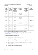
The following table is a guide to the maximum usable lengths of some common
cable types. Actual cable loss varies between manufacturers, there are many
variants, and the table is therefore based on typical data. Use it as a guide only
and refer to the manufacturer’s data sheet for your specific chosen cable for
accurate values.


