background image

INSTALLATION INSTRUCTIONS

Important!

These instructions are intended for qualified technicians.
The appliance must be installed correctly, in compliance with current laws.

Before carrying out any operation on the appliance, it must be disconnected from the
electricity supply.

Fitting the appliance in the worktop

The cooktop may be fitted into any worktop, as long as it is heat resistant (minimum temperature of
90°C).
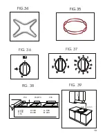
The dimensions of the hole to be made in the worktop and the minimum distances between rear
and side walls and those above the appliance are shown in figures 3

8

 and 3

9

.

Bear in mind that:

)

If the cooktop is installed without an oven below it, a separator panel must be placed between
the bottom of the cooktop and the housing below it, at a minimum distance of 10 mm.

)

If the cooktop is installed over an oven, place a separator panel at a minimum distance of 15
mm and follow the oven manufacturer's instructions, ensuring nonetheless sufficient aeration
as specified in fig. 

40

In any event, the electrical connection of the two appliances must

be carried out separately,

both for electrical purposes and to facilitate removal.

It is advisable to use an oven equipped with an internal forced cooling system.

Fixing the cooktop

To fix the cooktop in the housing, proceed as follows:

)

Position the special gasket supplied along the outer perimeter of the worktop, following the
diagram shown in fig. 3

8

, so that the ends of the gasket meet exactly without overlapping.

)

Position the cooktop into the worktop, taking care to ensure it is placed exactly in the centre.

)

Fix the cooktop to the worktop using the special brackets supplied, as shown in fig. 4

1

.

Correct installation of the sealing gasket ensures complete protection against infiltration of liquids.

Installation area and removal of combustion fumes

)

The appliance must be installed and operated in suitable areas, and in compliance with
current laws.

The installation technician must observe current laws governing ventilation and removal of
combustion fumes.

The air required for combustion is 2m

/h per kW of power (gas) installed.

Installation area

In the room where the gas appliance is installed, there must be a sufficient natural air supply to
allow the gas to burn correctly.
The natural flow of air must take place through an opening made on an outside wall of the room
and having a working section of at least 100 cm

2

(A). In the case of appliances without safety

valves, this opening must have a minimum working section of 200 cm

(fig. 4

2

).

This opening must be made in such a way that it cannot be obstructed from inside or outside. It
should be positioned near floor level, preferably on the side opposite the fume exhaust devices.
If it is not possible to make the necessary openings, the air can be supplied from an adjacent,
suitably ventilated room, as long as this room is not a bedroom, a dangerous area or a low-
pressure area.

Removal of combustion fumes

Combustion fumes produced by gas appliances must be removed by means of a hood connected
directly either to an exhaust duct or to the outside (fig. 4

2

).

8

Summary of Contents for built-in cooktops

Page 1: ...INSTRUCTIONS BOOKLET built in cooktops ...

Page 2: ......

Page 3: ...l safety can only be guaranteed if the product is connected to a suitable earth connection It is dangerous to modify or attempt to modify the appliance In the event of a malfunction do not attempt to repair the appliance yourself but contact a qualified technician After using the cooktop ensure the indicator on the knob is turned to the off position and close the mains gas delivery tap or the gas ...

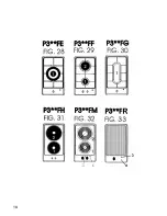
Page 4: ...ds to your appliance These initials together with the instructions in the following paragraphs and the illustrations at the back of the manual Fig1 33 will show the particular composition of your appliance An Example Approval mark Type P COOKING POINTS 60 cm cooktops with side controls Mod P6 L1 Fig 1 1 Semirapid right burner SR 2 Electric hotplate ø 145 3 Rapid burner R 4 Auxiliary burner A Mod P...

Page 5: ...r A 5 Triple crown burner TC Mod P9 F6 Fig 19 1 Rapid burner R 2 Semirapid left burner SR 3 Semirapid right burner SR 4 Auxiliary burner A 5 Fish kettle burner P Mod P9 FB Fig 20 1 Triple crown burner TC 2 Semirapid left burner SR 3 Semirapid right burner SR 4 Auxiliary burner A 5 Fish kettle burner P Mod P9 FC Fig 21 1 Rapid burner R 2 Semirapid left burner SR 3 Electric hotplate ø 145 4 Electric...

Page 6: ...sition To switch the burner off turn the knob clockwise to the position tap closed Burners with electric ignition Models with ignition switch To light one of the burners press the ignition switch and turn the corresponding knob to the maximum delivery position symbol Hold the switch down until the burner lights then adjust the flame by turning the knob to obtain the desired intensity Models with i...

Page 7: ...nd the knob holding down for about 4 5 seconds Then release the knob and adjust the flame by turning the knob to the desired intensity Using the grids The panstand grids are designed to make the appliance easy and safe to use Always check the panstand grids are properly positioned before using the appliance Furthermore always check the protective rubber feet are all present and correctly positione...

Page 8: ...eheating small amounts of liquids 3 4 5 6 Reheating larger quantities whipping creams and sauces 4 7 8 Simmering soups pasta risottos continuation of steaming cooking steaks and fries in general 4 5 8 9 10 Browning meats roast potatoes fried fish and for bringing large quantities of water to the boil 6 11 12 Brisk frying griddling steaks etc Type of hotplate The cooktop may be equipped with a conv...

Page 9: ...st iron pans Irregular bottoms can scratch the glass ceramic surface Check the bottom is clean and dry Do not use the cooktop if the surface is broken or damaged Bear in mind that the cooking zones remain hot for a relatively long time about 30 min after switching off Do not allow heavy or sharp objects to fall on the glass ceramic cooktop If you find a crack on the cooktop disconnect the applianc...

Page 10: ...ket meet exactly without overlapping Position the cooktop into the worktop taking care to ensure it is placed exactly in the centre Fix the cooktop to the worktop using the special brackets supplied as shown in fig 41 Correct installation of the sealing gasket ensures complete protection against infiltration of liquids Installation area and removal of combustion fumes The appliance must be install...

Page 11: ...power supply cable is suitable for the appliance load also stated on the data plate If the appliance is connected directly to the mains fit an all pole disconnect switch with minimum contact gap of 3 mm adequate for the appliance load and complying to regulations Do not use reducers adapters or switches for connection to the mains since these could overheat and cause burns Regulations require that...

Page 12: ...py water or specific detergents Never use abrasive cleaning products Dry thoroughly after cleaning Stainless steel top The stainless steel top should be cleaned with a damp cloth and proprietary detergents commercially available After rinsing dry preferably with a chamois leather Grids The enamelled panstand grids of the cooktop are dishwasher safe Stainless steel panstand grids may take on a blui...

Page 13: ...tenance nonetheless it is advisable to have them checked at least once every two years If the knobs become difficult to turn or if there is a smell of gas shut the gas supply tap and call After sales service Faulty taps must be replaced along with their gasket 11 ...

Page 14: ... sproeier A 1 00 0 30 0 50 SR 1 75 0 44 0 65 R 3 00 0 75 0 85 TC 3 30 1 50 0 91 P F 2 90 1 50 0 85 Only for Australian and New Zealand Tipo di gas gas type type de gaz tipo de gas tipo de gás gaz type G20 Pressione del gas gas pressure pression gaz presion gas pressão gas 1 0 kPa Bruciatori burners bruleurs quemodores bocas de gás branders Portata power inputs débit gas capacidad va zão debiet Max...

Page 15: ...gas 28 30 37 mbar Bruciatori burners bruleurs quemodores bocas de gás branders Portata power inputs débit gas capacidad va zão debiet Max kW Portata power inputs débit gas capacidad va zão debiet Min kW Ø Iniettore injectors injecteur inyector injector sproeier A 1 00 0 30 0 50 SR 1 75 0 44 0 65 R 3 00 0 75 0 85 TC 3 30 1 50 0 91 P F 2 90 1 50 0 85 Tipo di gas gas type type de gaz tipo de gas tipo...

Page 16: ...14 ...

Page 17: ...15 ...

Page 18: ...16 ...

Page 19: ...17 ...

Page 20: ...18 ...

Page 21: ...1 0 2 11 10 5 3 4 8 7 6 9 1 2 3 4 0 6 5 min 650 mm M i n 1 2 0 P90 P30 P60 P70 A 270 B 490 A 560 B 480 A 830 B 480 A A A B B B C C 55 19 FIG 34 FIG 35 FIG 37 FIG 38 FIG 39 FIG 36 ...

Page 22: ...C Min 3 mm D E Min 10 mm 20 FIG 41 FIG 40 FIG 42 FIG 43 FIG 44 FIG 45 ...

Page 23: ...nicos RAEE La correcta eliminación de este producto evita consecuencias negativas para el medioambiente y la salud El símbolo en el producto o en los documentos que se incluyen con el producto indica que no se puede tratar como residuo doméstico Es necesario entregarlo en un punto de recogida para reciclar aparatos eléctricos y electrónicos Deséchelo con arreglo a las normas medioambientales para ...

Page 24: ... dopadom na životné prostredie a ľudské zdravie ktoré by sa v inom prípade mohli vyskytnút pri nevhodnom zaobchádzaní pri likvidácii tohto výrobku Symbol na výrobku alebo na sprievodných dokumentoch znamená že s týmto výrobkom sa nesmie zaobchádzat ako s domovým odpadom Naopak treba ho odovzdat v zbernom stredisku na recykláciu elektrických alebo elektronických zariadení Likvidácia musí byt vykona...

Page 25: ...23 ...

Page 26: ...24 ...

Page 27: ......

Page 28: ...01Q038 ...

Reviews: