
www.tridonic.com
2
Subject to change without notice.
Data sheet
10/14-498-9
HID control gear
Electronic
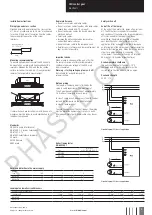
Circuit diagram PCI class 1 application
Standards
EN 55015 (radio interference)
EN 61000-3-2 (mains harmonics)
EN 61347-2-12
EN 61547 (interference immunity)
CE mark
EMV-VDE mark
ENEC mark
Radio interference
• Do not cross mains and lamp cables.
• Do not lay mains cables together with lamp cables
(ideally they should be 5–10 cm apart).
• Do not lead mains cables too closely along the
electronic ballast.
• Twist lamp cables.
• Increase the distance between lamp cables
and earthed metal surfaces.
• Keep the mains cable in the luminaire short.
• Parallel runs (x) of mains and lamp cables must be
kept as short as possible.
Note on wiring
The length of the lamp wires is limited by the
value of cable capacitance. The maximum of
120 pF would enable connection of approximately
1.5 metres of lamp wire for each lamp.
In class 1 luminaires it is necessary to earth the bal-
last and the luminaire via the earth terminal,
in class 2 luminaires not.
To avoid the damage of the control gear, the wiring
must be protected against short circuits to earth
(sharp edged metal parts, metal cable clips, louver,
etc.).
Important advise
When a lamp is changed (at the end of its life),
if a lamp is missing or after overtemperature
shut down the mains voltage of the ECG must
be disconnected.
Warning – starting voltage up to max. 5 kV!
Not suitable for use with lamps with
integral ignitors.
Circuit diagram PCI class 2 application
Installation instructions
Wiring type and cross section
Stranded wire with end ferrule with a cross section
of 1.5 mm
2
or solid wire up to 2.5 mm
2
may be used
for wiring. Strip 6 mm of insulation from the cables
to ensure perfect operation of the screw
terminals.
6 mm
wire preparation:
0.5 – 2.5 mm²
luminaire
PCI
luminaire
gap
PCI
Mounting recommendation
To ensure optimum heat removal the ECG should
be mounted on a metal plate (luminaire body) No
insulators between the ECG and the the cooling
surface (air, adhesive tape, etc.). Finally important
remains the temperature measurement.
Safety switch off
End of life of the lamps
At the end of their useful life, lamps often cycle on/
off. The PCI ballast recognises this condition
and switches off the lamp, after three complete on/
off cycles and whilst the supply has been
unswitched. Complete lamp switch off enables
easy identification of a defective lamp in the
application. After a change of the faulty lamp and
an interruption of the mains supply (mains reset) the
ballast will strike the lamp. When there is no lamp in
circuit or a defective lamp is connected
to the ballast, the ballast will switch off after apr.
25 minutes (3.5 minutes of ignition time).
Overtemperature shutdown
The units shut down at
D
t approx. +10 °C
compared with tc/ta. A mains reset must be
carried out so that the units switch on again.
Overload strength
320 V
AC
/ 1 h
If several ballasts are installed in masts, boxes, etc.,
measures must be taken to avoid overheating of
individual components.
Loading of automatic circuit breakers
Automatic circuit breaker type
C10
C13
C16
C20
B10
B13
B16
B20
Installation
Ø
1.5 mm
2
1.5 mm
2
1.5 mm
2
2.5 mm
2
1.5 mm
2
1.5 mm
2
1.5 mm
2
2.5 mm
2
PCI 2/35
14
25
36
42
8
14
18
18
PCI 2/70
7
14
20
20
4
6
7
7
Harmonic distortion in the mains supply
Ballast
Type
THD
3
5
7
9
11
PCI 2/35
7.5
6.0
3.5
3.5
3.5
1.5
PCI 2/70
7.5
4.5
5.0
2.5
2.5
1.0
Ballast lumen factor
EN 60929 8.1
Type
AC/DC BLF
at U = 198-254 V, 25 °C
PCI 2/35
1.0
PCI 2/70
1.0
PHASED
OUT


