background image

215-293-0700 

7


215-293-0701

[email protected]

3

Installation and Operation Guide

Proven

Priming

Performance

AirPrime

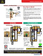
 - How Does It Work

NFPA #1901 and #1906

 – Fully Compliant to Standards

Pump Panel Noise Level – 

Lowest

 dB in the Industry

Strainer Debris Cleanout Plug

Air In 
From Chassis
Air Brake
System

Used For Additional Priming 
Points To Be Pre-Primed

Vacuum Inlet from

Priming Points

Discharged Air/Water Out

Manifold

Control Solenoid

Piston Valve
Opens With
Air Pressure

Orange Arrows…
Air Flows Through
The Primer Body In 3 
Stages for Maximum 
Flow and Vacuum.
The Venturi Action 
Creates the Vacuum 
to Prime the Pump.

1

2

3

White Arrows 
Indicate Debris 
Collection Area

How Does It Work?

AirPrime


utilizes air supplied from the chassis air brake system 

to operate the fire pump primer. This is proven to be far more 
efficient and reliable than rotary vane primers driven by an electric 
motor.

AirPrime


virtually eliminates the impact load on the electrical 

system and improves vehicle reliability.

AirPrime


also improves performance in the elapsed time for 

establishing water supply. This results in improved fire ground 
operations and safety.

Auto Prime


Depress switch into the upper position. The Green 

LED light will illuminate while priming occurs. The primer will only 
activate when the 

OK TO PUMP

 light is 

ON

 and the Pump Pressure 

is below 20 PSIG.

AirPrime

 Primers can be used for both 

New

 and 

Retro-Fit

 installations. In Retro-Fit scenarios, an 

AirPrime

 replacement installation 

requires minimal tools and time. Automatic 

AirPrime

 models provide instant re-priming of the pump when required.

A worn out rotary vane primer can be easily replaced by an 

AirPrime


unit with 

Automatic

 or 

Manual


control.

Auto Prime Position

Off Position

Primer switch shown 
in


OFF


position. LED 

indicator light is


OFF

.

Switch will illuminate 
while the primer is 
operating while in the 

AUTO PRIME

 position.

Primer switch shown in 

AUTO PRIME


position. 

Green LED indicator light 
is


ON 

when priming

.

1.  Press switch 

DOWN


and 

hold

 for 

Manual


Prime

.

2.  Press switch 

UP

 for 

AUTO PRIME

.

3.  Center position is 

OFF

.

1

4

" NPT Air Supply Inlet

1

4

" NPT Air Supply Inlet

To  

Water Pump 

Priming Point

Discharged Air

To  

Water Pump 

Priming Point

Air supply inlet from 
chassis brake system is


CLOSED

.

Incoming Air Flow


OFF

.

Air supply inlet from 
chassis brake system is 

OPEN

Air enters and 

activates primer.

Incoming Air Flow 

ON

.

OK TO PUMP

Click Here

 for the 

AirPrime

 Retrofit Guide

Click to view

AirPrime 

Animation

Summary of Contents for AirPrime SC 1906 Wildland Unit

Page 1: ...nd Operation Guide All AirPrime Models Automatic Controls Manual Controls t Lift Gauge Option Standard Control q Lift Gauge Option u q Standard Control AIRPOWER SC 1906 Self Contained Priming System AirPrime Pressure Regulator For use with high pressure SCBA cylinders ...

Page 2: ... for small trucks without air brakes See Page 5 for additional information 7 Industrial AirPrime units are available for large fire pumps Contents Available Models 2 AirPrime Overview 2 AirPrime How Does It Work 3 Installer Responsibilities 4 Air Schematic PPV Air Hose and Connections 5 Automatic Single Location AirPrime System 6 Automatic Single Location AirPrime System with Optional Vacuum Gauge...

Page 3: ...ns and safety Auto Prime Depress switch into the upper position The Green LED light will illuminate while priming occurs The primer will only activate when the OK TO PUMP light is ON and the Pump Pressure is below 20 PSIG AirPrime Primers can be used for both New and Retro Fit installations In Retro Fit scenarios an AirPrime replacement installation requires minimal tools and time Automatic AirPri...

Page 4: ... sparingly while applying sealant to avoid blockage of the internal mesh filter See Page 5 Figure 5 Remote Primer Mounting 1 A fabricated primer bracket to secure the primer within the pump enclosure The mounting height for all priming components must be ABOVE the highest priming point on the pump suction side or above the highest remote priming valve for multiple location systems to permit air re...

Page 5: ...f any kinks or bends and must not be run near exhaust components or rotating shafts Stay 6 150 mm away from any exhaust or hot components Use rubber grommets to protect the tubing from sharp metal edges at all hole locations When the installed length of the air brake tubing exceeds 20 feet 6 1 m a minimum size of 1 2 OD air brake tubing should be used Pressure Protection Valve PPV A Pressure Prote...

Page 6: ...rPrime rocker switch in AUTO PRIME mode If drafting connect all suction hoses strainer and tighten accordingly Utilize wheel chocks In Cab Apply parking brake Engage pump per manufacturers recommendations AirPrime will start priming automatically when the pump is engaged NOTE Never run a fire pump dry for more than 45 seconds Pump Panel Verify that the green OK TO PUMP light is ON and then increas...

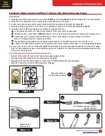
Page 7: ... constant 12 24 volt vehicle power source Connect Black to chassis ground on the vehicle Wires 1 foot long wiring and 1 amp fuse by installer Plug the Male Deutsch connector into the Female Deutsch connector on the AirPrime solenoid 5 feet of cable 1 8 m Connect to the Male Deutsch connector on the pump discharge pressure switch 5 feet of cable 1 8 m See Figure 6 on Page 6 6 Connect a 1 4 OD 6 35 ...

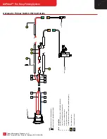
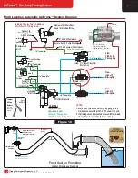
Page 8: ...2 Circled Letters Used To Identify Wire Descriptions PLUG IN TO AirPrime Solenoid Black Positive and White Negative Red Wire to 12 24V Power Source Black Wire to Chassis Ground White Wire To Positive Side of OK TO PUMP Light Circuit Automatic AirPrime Assembly 1 2 6 5 1 3 5 6 3 Automatic AirPrime Panel Switch A C B D E 2 LETTER A B C D E Discharge Pressure Switch Male Deutsch Connector Female Deut...

Page 9: ...ol Manual AirPrime Second Control Point In Cab Valve Depress to Activate 3 4 Tubing Minimum PlumbTo DrainValve Strainer 3 8 Tubing Minimum 3 8 Tubing Minimum 3 8 Tubing Minimum Closed Compressed AirIn PumpPanel Valve FirePump Open 3 8 Tubing Minimum Color Key Air Supply Lines Vacuum Priming Lines InCab Valve FirePump From FirePump PrimingPoint ...

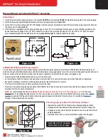
Page 10: ... button will operate the primer regardless of whether the fire pump is engaged or not Depressing the Push To Prime button directs air to the primer inlet An internal valve to the fire pump is opened with air pressure from the chassis air brake system when the button is depressed Vacuum for drafting is created by air flowing through multi stage internal venturi nozzles The Primer Control Valve has ...

Page 11: ...for LEFT RIGHT FRONT and REAR remote priming locations as shown in Photo 6 8 See Photos 3 and 4 to note that the cast in arrows on the RPVs and Check Valves are in the proper flow direction Operating Instructions for Multi Location Automatic Priming System 1 See operating instructions for the Auto Priming System on Page 6 for the initial fire pump priming procedures 2 Be sure the AirPrime switch i...

Page 12: ... Min 3 8 Tubing Min Drawing Denotes Two 2 Additional Multi location Priming Points Check Valve Panel Rocker Switch Auto AirPrime Color Key Electric Lines Air Supply Lines Vacuum Priming Lines Multi Location Wiring Harness 3 4 Tubing Min See photo inset lower left corner Open Position Out Figure 16 Color Key 3 4 ID External Flex Line 3 4 ID External Flex Line 3 4 ID External Flex Tubing Merge All H...

Page 13: ...ocation Color Key 3 4 ID External Flex Line to Low Point Drain 1 2 ID Internal Flex Line 3 4 ID External Flex Lines 1 2 or 5 8 ID External Flex Line 1 2 ID Internal Flexible Tubing Priming Line Drain Valve 1 2 or 5 8 ID External Flexible Tubing 3 4 Weld Coupling 3 4 ID External Flex Tubing Merge All High Point Pickups At The Valve Location Higher Than The High Points Fittings In Kit From Outside O...

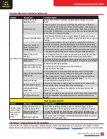
Page 14: ...an or replace Part 21 002 0 b Automatic AirPrime Remove air supply piping remove air solenoid assembly remove fine mesh filter clean or replace Part 21 002 0 Slight air leak in discharge or intake valves in fire pump plumbing c Hydrostatic test the plumbing system to the NFPA 1901 standard with wet fire pump closed valves 250 PSIG 17 2 Bar for 10 minutes without pressure loss Check the interior ch...

Page 15: ... suction intakes a Remove the MIV and cap intake b Install a cap on the discharge side of the relief valve c Cap the Storz or NH intake Check the AirPrime internal priming valve a The priming valve is not seating in the shut off position remove primer disassemble and check the priming valve spring seat and operation b The priming valve is stuck Check for damaged O Ring or check to see that the pis...

Page 16: ... is performed as follows 1 Set up the apparatus in accordance with the pump test outlined in the NFPA 1901 Standards 2 Engage the pump and increase the throttle to a maximum engine speed of 1000 RPM 3 Operate the AirPrime with the air system over 100 PSIG 7 0 Bar pressure air tanks filled to capacity and at 1000 RPM engine speed For the Manuallly controlled primer release the push button when a di...

Page 17: ...r damage shall in no case exceed the price paid for the product or any part thereof which give rise to claim As always TRIDENT technical assistance and support is available for your convenience 5 Year Warranty For five years after the date of purchase Trident Emergency Products LLC warrants its products to be free from defects in materials and workmanship when properly installed operated and maint...

Page 18: ...Trident Emergency Products LLC 2940 Turnpike Drive Suite 9 Hatboro PA 19040 USA 18 AirPrime Fire Pump Priming System Installation Operation Notes Vehicle Number ...

Page 19: ... 215 293 0700 7 215 293 0701 sales tridentdirect com 19 Installation and Operation Guide Proven Priming Performance Installation Operation Notes Primer Testing Notes ...

Page 20: ...iming Valve RPV 30 035 1 23 1 4 NPT Air Check Valve 30 012 0 24a Remote Priming Valve with 12 Volt Solenoid 30 035 10 24b Remote Priming Valve with 24 Volt Solenoid 30 035 11 25 Multi Location Push Button w Mounting Plate 27 003 9 26a Label Only PRIMER FRONT INTAKE 02 006 5 26b Label Only PRIMER REAR INTAKE 02 006 6 26c Label Only PRIMER LEFT SIDE 02 006 7 26d Label Only PRIMER RIGHT SIDE 02 006 8...

Reviews: