background image


Table of contents 


1.Health and safety precautions:   


1.1 General: 


1.2 Electrical/maintenance 


1.3Installation:   


2. Transporting, unloading and storage of tanks: 


3. Introduction:   


4. The wastewater purification process: 


4.1 Stage 1: Existing primary settlement chamber: 


4.2 Stage 2:Aeration (treatment) chamber:   


4.3 Stage 3:Final settlement chamber: 


5. Plant dimensions: 


6. Plant drawings: 


10 

7.Technical drawings of Tricel pumped plant: 


14 

8.Lid locking points: 


14 

9.Manhole risers (deep inverts):   


15 

10. Installation: 


16


10.1 Pre-installation tank inspection: 


16 


10.2 Quick installation guidelines:   


17 


10.3 Detailed installation information: 


18 


10.3.1 Excavation size: 


19 


10.3.2 Eexcavation dept:   


20 


10.3.3 Loadings:   


21 


10.3.4 Control of groundwater 


21 


10.4 Gravel installation:   


21 


10.4.1 Tank base/plinth:   


22 


10.4.2 Installing onto the base/plinth: 


22 


10.4.3 Backfilling dry site   


22 


10.5 Concrete installations: 


23 


10.5.1 Tank base/plinth:   


23 


10.5.2 Installing onto the base/plinth: 


23 


10.5.3 Backfilling a wet site: 


24 


10.6 Plinth and backfill specifications: 


25 


10.6.1 Gravel backfill specifications 


25 


10.6.2 Concrete backfill specifications: 


26 


10.6.3 Top soil   


26 

11. Electrical installation:  


27 

12. Plumbing the system:  


27 

13. Ancillary installation notes: 


28 


13.1 Ventilation:   


28 


13.2 Control housings: 


28 


13.3 Access: 


28 

14. Plant operation: 


29 

15. Disposal of treated water: 


29 

16. Maintenance:  


30 


16.1 Regular maintenance: 


30 


16.2 


16.2.1 Yearly service (available from your supplier):   


30 


16.3 Production of sludge:  


31 

17. Operation conditions:  


32 

18. Troubleshooting: 


33 

19. Certification:  


37 


TTM T103 Rev04 – 08 April 2014 


Summary of Contents for Duos P10

Page 1: ...1...

Page 2: ...3 Loadings 21 10 3 4 Control of groundwater 21 10 4 Gravel installation 21 10 4 1 Tank base plinth 22 10 4 2 Installing onto the base plinth 22 10 4 3 Backfilling dry site 22 10 5 Concrete installati...

Page 3: ...are for pedestrian use only Never enter a tank unless qualified to do so Naked flames shall not be used in the vicinity of the tank due to the danger of combustion The manhole covers shall never be le...

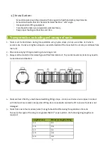
Page 4: ...p or roll tanks from the truck 2 Move tanks only by lifting and setting do not drag or roll 3 Always set the tank s on flat smooth ground free from debris etc To prevent movement tanks may need to be...

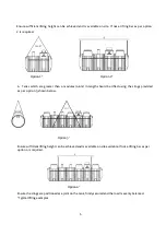
Page 5: ...4 modules 4 6m in length should be lifted using the slings provided as per option 3 shown below Option 3 Ensure sufficient lifting height can be achieved and is available on site available If not a li...

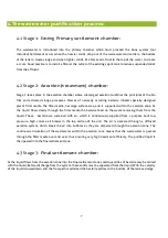
Page 6: ...omponents and these modules are fabricated together to make different size tanks The Tricel Duos Submerged aeration system is suitable for domestic and light commercial applications These plants use a...

Page 7: ...e aeration zone As the liquid flows slowly through the filter media the bacteria feed on the waste removing them from the liquid These bacteria are sustained with air which is continuously supplied fr...

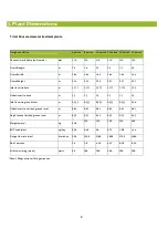
Page 8: ...375 1 375 1 375 1 375 1 35 Outlet invert to base m 1 3 1 3 1 3 1 3 1 3 1 3 Inlet invert to ground level m 0 535 0 535 0 535 0 535 0 535 0 56 Outlet invert to finished ground level m 0 61 0 61 0 61 0 6...

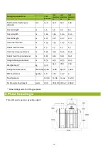
Page 9: ...to base m 1 3 1 3 1 3 1 3 Inlet invert to ground level m 0 56 0 46 0 46 0 46 Outlet Invert to ground level m 0 61 0 61 0 61 0 61 Height above ground level m 0 35 0 35 0 35 0 35 Weight empty kg 550 65...

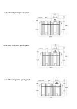
Page 10: ...11 Tricel Duos 8 person gravity plant Tricel Duos 10 person gravity plant Tricel Duos 12 person gravity plant...

Page 11: ...12 Tricel Duos 18 person gravity plant Tricel Duos 24 person gravity plant Tricel Duos 30 person gravity plant...

Page 12: ...13 Tricel Duos 36 person gravity plant Tricel Duos 42 person gravity system Tricel Duos 50 person gravity system...

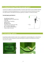
Page 13: ...ecification Min discharge rate 60l min Continuous duty with 35 C liquids fully submerged Dry motor class F insulation IP68 protection Max immersion 5m Single phase 220 240 V 50 Hz 2 poles 0 55 to 1 1...

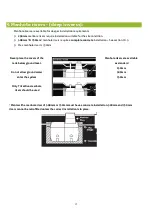
Page 14: ...installation See section 10 5 r Max manhole riser is 750mm Never place the covers of the tank below ground level Do not allow ground water enter the system Only Tricel Duosmanhole risers should be us...

Page 15: ...m as per picture The Tricel Duos is not suitable where a deeper installation is required 10 1 Pre installation tank inspection Tanks should be visually inspected for damage which may have occurred dur...

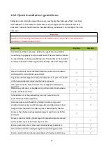
Page 16: ...cordance with supplier s instructions See section 2 Dig a hole 500mm larger than the plant dimensions in plan The depth of the hole will be determined by the inlet pipe level If the plant contains mor...

Page 17: ...higher than the max ground level line Compact evenly around the tanks to ensure it s is properly supported An access chamber should be installed before and after the tank for sampling and to assist in...

Page 18: ...ired between adjacent tanks Unstable ground with excessive sand peat swamps etc may require larger excavations The excavation should be maintained dry by pumping or whatever suitable means Total excav...

Page 19: ...for the minimum base thickness shown Dimension details of the tank are shown on the relevant drawing given in section 6 Ground instability e g running sand may necessitate over excavation and stabiliz...

Page 20: ...tallation guidelines are available on www ie tricel eu 10 3 4 Control of groundwater During installation tanks must not be subjected to buoyant forces Incorrectly installed tanks that are subject to m...

Page 21: ...Ballast the plant by filling each chamber with clean water to a depth of 300mm and recheck the pipe work levels Commence backfilling with gravel as per section 10 5 1 in layers of 225mm evenly around...

Page 22: ...s and boulders The base is constructed of a 50mm layer of suitably compacted gravel covered with a 250mm layer of semi dry concrete Refer to 10 6 2 Ensure that base is level and at the correct height...

Page 23: ...lling the chambers whilst backfilling ensure that the progressive water level is no more than 300mm above the backfill level Backfill with concrete until it has reached the invert of the outlet pipe C...

Page 24: ...ls are approved as primary backfill Rounded pea gravel Minimum particle size 3mm maximum 18 mm compacted to a relative density of 70 Gravel shall be clean and free flowing free from large rocks dirt s...

Page 25: ...rounding concrete Where necessary this may be extended to include light internal vibration Never use deep revibration which will substantially increase the pressure on the tank possibly causing failur...

Page 26: ...ed 230V 30mA The cable armor must be properly bonded to the main earth at the premises Never disconnect the power to the air pump It is imperative that it is running 24 hours a day every day 12 Plumbi...

Page 27: ...owers or pumps if supplied may be placed into separate control housing These can be fitted with visual audio alarms along with other equipment If so a mains supply may be required Mains must be discon...

Page 28: ...alled and operational it is important that it s commissioned by our service team or a Tricel Duos distributor to ensure it is working effectively A commissioning certificate will then be issued to the...

Page 29: ...ees a fresh supply of air to the air blower The vent under the de sludging cover allows gas to escape and stops the tank from becoming pressurized All vents should be checked to make sure they are not...

Page 30: ...esludged periodically but a maximum every 3 years The two chambers either side of the aeration chamber must be emptied and refilled with water De sludging is done with a vacuum tanker we recommend the...

Page 31: ...h an effluent filter at the outlet An electrical connection to the plant must be maintained for it to function correctly This ensures that the plant has a continuous air supply and where necessary the...

Page 32: ...ermittently or if extended periods of non use are expected it is recommended that the p l a n t remain on and in operation The contents of the p l a n t should not be allowed to go septic due to non u...

Page 33: ...mp malfunction An electrician should check the power supply to the plant Clean out impellers or replace pump Ensure pump is disconnected from the mains before you attempt to unclog it Find blockage an...

Page 34: ...disposal system clogged Storm water flooding Pump not working Contact installer to repair sub surface disposal system Percolation area Redirect storm water drains Storm water must never enter the syst...

Page 35: ...causes Corrective action Effluent odour directly outside the house or inside the house Pipe connections to toilets drains not connected correctly Air vent on pipe work not fitted or fitted incorrectly...

Page 36: ...Duos passed all structural testing crush test durability test carried out by PIA staff Water tightness tests were performed by PIA at our headquarters on the range of tanks up to P50 successfully pas...

Page 37: ...38...

Reviews: