Due to continuous improvement, Triatek reserves the right to change product specifications without notice.
FMS-1655L Room Pressure Controllers
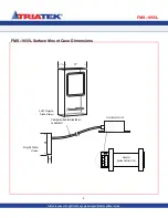
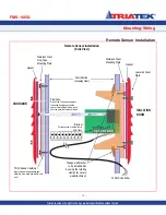
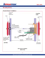
ordered with a remote sensor must be installed
in the wall between the isolation room and the
adjoining corridor. Port P1 must be oriented
towards the isolation room and Port P2 toward
the corridor. Please see illustration on page 13.
With this sensor orientation, a positive
pressure value indicates that the isolation
room is positive with respect to the corridor.
NOTE: A three conductor cable must be
connected between the remote sensor and
the FMS-1655L. Maximum length of this
cable is 1,000 feet.
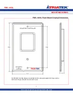
The display unit can be installed outside the
room, at the nurses station, in the engineering
office, or at any other location as needed.
Mounting Steps:
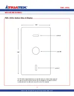
1. Cut an opening in the wall of the isolation
room for the single-gang low voltage
bracket and remote sensor electronics.
Nominal hole dimensions are 3.65” H x
2.15” W.
2. Drill a
16” hole through the opposite wall
for the flow tube as shown.
3. Bring the 3-conductor signal wire through
the cut-out.
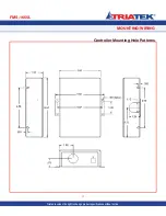
4. Install the single-gang low voltage
mounting bracket in the cutout. Route a
length of supplied flow tube through the
mounting bracket and through the 7/16”
hole in the opposite wall.
5. Push a length of 3-conductor cable
from the FMS-1655L controller down
wall to the opening of the single-gang
low voltage mounting bracket. Connect
cable wires to +Vin, GND, and IO at the
sensor’s 9 pin connector.
6. Attach the flow tube to the sensor port,
then push the tube and sensor module
into place and secure to the mounting
enclosure with two 6-32 x 3/4 screws
supplied.
7. Install the louvered cover plate.
8. On the opposite side (corridor) attach the
flow tube to the barbed fitting of the flow
tube mounting plate.
9. Press the mounting plate into place,
allowing the excess tube length to go into
the wall space. Secure with the screws
and anchors.
10. Install the louvered cover plate.
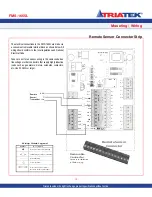
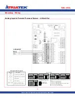
11. At the FMS-1655L controller, connect the
three leads from the remote sensor to
the terminals V, AI_1, and GND.
Remote Vin goes to terminal
+V, remote sensor IO goes to terminal
AI_1, and remote sensor GND goes to
controller GND.
Install jumper on pin 1 JP6 and JP3 see
diagram on page 15 (If not installed at the
factory).
12. If configured for dual sensor mode, repeat
steps 1 through 10 for the secondary
remote sensor and proceed to step 13.
13. At the FMS-1655L controller, connect the
three leads from the secondary remote
sensor to the terminals V, AI_2,
and GND. Remote Vin goes to
teV, remote sensor IO goes to
terminal AI_2, and remote sensor GND
goes to controller GND.
Mounting/Wiring
Remote Sensor Installation
FMS-1655L
-
12
-
Triatek reserves the right to change product specifications without notice.


