background image

HMG Delta CLASSIC Replacement Kit

Electronic Spark Ignition

3

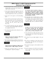
2. Insert the pilot orifice into the pilot hood and

tighten with a wrench.  No thread sealant is nec-
essary for the connection.

3.  Insert the Grounding Rod through the bottom of

the Pilot Hood / Bracket Assembly.  Attach the rod
clip onto the pilot hood / orifice to secure the rod.

4.  Place the (3) 3/8” spacers over the Grounding

Rod.

5.  Insert the Electrode through the Pilot Hood /

Bracket assembly and over the Grounding Rod.
Place the 3/4” spacer between the bracket
assembly and the ceramic body of the
Electrode.

6.  To secure the Electrode into place tighten the

set screws onto the Grounding Rod using the L-
key supplied with the kit.

7.  Reconnect the ignition cable to the pilot / elec-

trode assembly.

Inspect and ensure the ignition cable is free
of damage.  Replace as needed.

8.  Reconnect the pilot gas tubing to the pilot ori-

fice.  Ensure the pilot tubing is tight and secure

Inspect and ensure the pilot gas tubing is free of
damage, breaks or kinks.  Replace as needed.

9.  Check the insulation gasket on the burner

mounting plate.  Replace if damaged.

If the burner plate insulation is damage or
show signs of deteroration, replace the insu-
lation gasket.  Failure to replace a damage
insulation gasket can cause flue gas leakage
for the burner assembly, resulting in severe
personal injury or death

10. Remount the burner assembly into the combus-

tion chamber.  Use care not to damage the burn-
er mounting plate insulation, pilot gas tubing or
the spark ignition cable when inserting the
burner assembly into the combustion chamber.

Extreme care must be given when inserting
the burner assembly into the combustion
chamber to prevent damage to the insulation
gasket, pilot gas tubing and ignition cable.

11. Secure the burner assembly using the (2) 17mm

mounting nuts located to the left and right side
of the windbox.

12. Reconnect the gas supply piping to the gas

valve.  

13. Re-seat the combustion air inlet tube onto the

blower flange.  Reconnect the air inlet piping to
the unit as needed.

14. Reconnect the snap-set on the right side of the

windbox.

15. Open the main gas valve shut-off valve and per-

form a leak test at all gas piping connections
near the unit.

WARNING

WARNING

WARNING

WARNING

WARNING

Summary of Contents for PGRKIT25

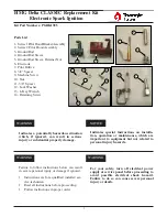
Page 1: ...ubstantial property damage Indicates special instructions on installa tion operation or maintenance which are important to equipment but not related to personal injury hazards NOTICE WARNING 1 2 4 5 7 3 6 11 13 12 10 9 14 8 Failure to follow instructions below can result in severe personal injury or damage if ignored Instructions are for a qualified installer ser vice technician Read all instructi...

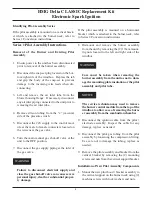
Page 2: ...hut off valve at the unit to the OFF position 7 Disconnect the gas supply piping at the inlet of the gas valve Failure to disconnect electrical supply and close the gas shut off valve can cause severe personal injury death or substantial proper ty damage 8 Dismount and remove the burner assembly from the unit by removing the 2 17mm mount ing nuts located to the left and right side of the windbox C...

Page 3: ... 9 Check the insulation gasket on the burner mounting plate Replace if damaged If the burner plate insulation is damage or show signs of deteroration replace the insu lation gasket Failure to replace a damage insulation gasket can cause flue gas leakage for the burner assembly resulting in severe personal injury or death 10 Remount the burner assembly into the combus tion chamber Use care not to d...

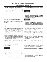
Page 4: ...ry death or substantial proper ty damage 6 Dismount and remove the burner assembly from the unit by removing the 2 17mm mounting nuts located to the left and right side of the windbox Care must be taken when removing the burner assembly from the unit as not to dam age the mounting plate insulation or the pilot assembly and pilot tube The service technician may need to remove the burner control mod...

Page 5: ... deterioration replace the insu lation gasket Failure to replace a damage insulation gasket can cause flue gas leakage for the burner assembly resulting in severe personal injury or death 11 Remount the burner assembly into the combus tion chamber Use care not to damage the burn er mounting plate insulation pilot gas tubing or the spark ignition cable when inserting the burner assembly into the co...

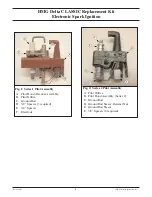
Page 6: ...Fig 2 Series 2 Pilot Assembly A Pilot Orifice B Pilot Hood Assembly Series 2 C Ground Rod D Ground Rod Sleeve Retainer Nut E Ground Rod Sleeve F 3 8 Spacers 2 required Fig 1 Series 1 Pilot Assembly A Pilot Hood Bracket Assembly B Pilot Orifice C Ground Rod D 3 8 Spacers 3 required E 3 4 Spacers F Electrode ...

Reviews: