background image

19

EN

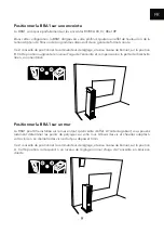
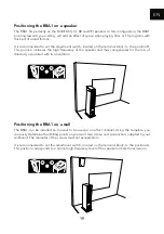
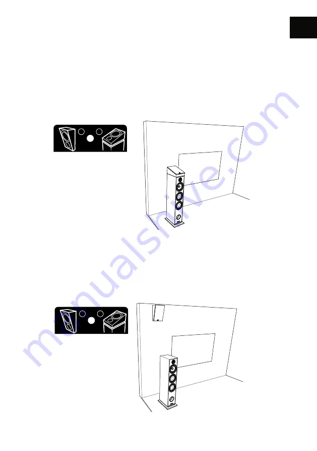
Positioning the BRA1 on a speaker

The BRA1 fits perfectly on the BOREA 03, 07, 08 and 09 speakers. In this configuration, the BRA1 
pointing towards your ceiling, will add an effect of space when playing films or TV programs with 
this kind of sound format.

It is recommended to set the adjustment switch, located on the terminal block, to the position B. 
This position increases the high frequency of the speaker and thus compensates for the loss of 
directivity associated with its orientation.

Positioning the BRA1 on a wall

The BRA1 can be installed on the wall to be used as an effect channel. Using the template, you 
can easily determine the drilling points on your wall. Use screws and wall anchors adapted to your 
wallboard. The diameter of the screws must not exceed 4mm.

It is recommended to set the adjustment switch, located on the terminal block, to the position A. 
This position corresponds to a normal high-frequency level of the speaker in direct transmission.

A

B

A

B

A

B

A

B

Summary of Contents for BOREA BR02

Page 1: ...BOREA Mode d emploi Garantie Owner s manual Warranty TRIANGLE DISTRIBUTION FRANCE 301 Avenue Flandres Dunkerque Z I Les Etomelles 02200 Villeneuve Saint Germain FRANCE ...

Page 2: ......

Page 3: ...nts pour une configuration home cinéma 12 Î Placement pour le home cinéma 13 USER MANUAL ENGLISH 15 Î Unpacking 16 Î Assembly 17 Î Connections for stereo setup 20 Î Stereo positionning 21 Î Connections for home theater setup 22 Î Home theater positionning 23 INFORMATIONS TECHNIQUES TECHNICAL INFORMATIONS 26 GARANTIE WARRANTY 28 INSTRUCTIONS DE SÉCURITÉ SAFETY INSTRUCTIONS 30 ...

Page 4: ......

Page 5: ...5 FR MODE D EMPLOI FRANÇAIS ...

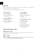
Page 6: ... revendeur Avant de jeter les emballages vérifiez qu il ne reste rien à l intérieur Contenu pack BRC1 Î 1 x voie centrale Borea Î 1 x grille de protection Î 4 x plots caoutchouc adhésifs Î 1 x mode d emploi Contenu pack BR02 BR03 Î 2 x enceintes Borea Î 2 x grilles de protection Î 8 x plots caoutchouc adhésifs Î 1 x mode d emploi Contenu pack BRA1 Î 2 x enceintes BRA1 Î 2 x grilles de protection Î...

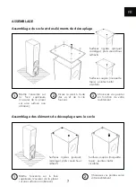
Page 7: ...e non abrasive Vissez le pied à l aide des vis et de la clé fournies Choisissez vos pointes en fonction de votre revêtement 1 2 3 Assemblage des éléments de découplage sans le socle Surfaces rigides parquet carrelage plots caoutchouc adhésifs Surfaces souples moquette tapis pointes métal vissables Mettre l enceinte sur la face supérieure s assurer de la placer sur une surface non abrasive Choisiss...

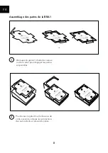
Page 8: ... de la BRA1 1 Découpez le gabarit à l aide de ciseaux ou d un cutter pour dégager les parties en pointillés Positionnez le gabarit sur le dessous de votre enceinte enlevez les protections des autocollants et placez les patins 2 ...

Page 9: ...osition augmente le niveau d aigu de l enceinte et compense ainsi la perte de directivité liée à son orientation Positionner la BRA1 sur un mur La BRA1 peut être installée sur le mur en tant qu enceinte d effet À l aide du gabarit vous pouvez aisément déterminer les points de perçages sur votre mur Utilisez des vis et chevilles adaptés à votre cloison Le diamètre des vis ne doit pas dépasser 4mm I...

Page 10: ...conçu pour le branchement d enceintes acoustiques Utilisez des longueurs de câble identiques pour les voies droite et gauche Veillez à respecter les polarités et pour chaque voie Ne pas oublier de dénuder les câbles si nécessaire AUDIOIN CD AUX RECORDER PHONO SIGNAL GND AC IN AUDIOO UT PREO UT RECORDER ...

Page 11: ... les enceintes de manière à ce qu elles diffusent le son dans le sens de la longueur de la pièce Î Évitez le placement dans les coins de la pièce Il favorise l excitation des résonances propres à la pièce Pour une colonne laissez un espace minimum de 40 centimètres entre le mur et l enceinte Jouez sur le positionnement des enceintes par rapport au mur arrière Généralement une position proche du mu...

Page 12: ... les voies droite et gauche puis dénuder les extrémités Veillez à respecter les polarités et pour chaque voie Î Débranchez votre amplificateur du secteur lors du branchement de vos enceintes Veuillez vous référer au manuel de votre amplificateur pour la connexion de vos enceintes et leur attribution en fonction de leurs positions dans votre pièce Î L illustration ci dessous peut être différente du...

Page 13: ...s l extrême grave qui est enregistré sur des supports tels que les DVD audio ou vidéos Son placement n est pas critique si vous sélectionnez une fréquence de raccordement avec les voies principales en dessous de 80Hz Au delà de cette fréquence il faut mieux rapprocher le caisson des enceintes principales la position optimale étant entre celles ci Î Il est conseillé de placer les voies arrières ent...

Page 14: ...14 EN SUGGESTIONS DE COMPOSITION HOME CINÉMA Configuration 5 1 2 Configuration 7 1 2 ...

Page 15: ...15 EN USER MANUAL ENGLISH ...

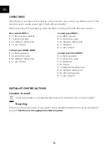
Page 16: ... adhesive rubber plots Î 1 x user manual Content pack BRA1 Î 2 x BRA1 speaker Î 2 x protections grids Î 8 x adhesive rubber plots Î 1 x template Î 1 x user manual Content pack from BR07 Î 2 x Borea speakers Î 2 x protections grids Î 2 x pedestals Î 8 x screws Î 1 xpedestal mounting tools Î 8 x adhesive rubber plots Î 8 x decoupling spikes Î 1 x user manual INSTALLATION PRECAUTIONS Location to avoi...

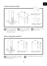
Page 17: ...ce it on a non abrasive surface Screw the pedestal using the supplied key and screws Choose spikes according to your ground 1 2 3 Spike assembly without pedestal Rigid ground wood floor adhesive rubber pads Soft ground carpet rug metal spikes screwed Place your loudspeaker on the upper face be sure to place it on a non abrasive surface Choose spikes according to your ground 1 2 ...

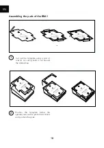
Page 18: ...ng the pads of the BRA1 1 Cut out the template using a pair of scissors or a utility knife to cut around the dotted line Position the template below the speaker remove the protective stickers and position the pads 2 ...

Page 19: ... frequency of the speaker and thus compensates for the loss of directivity associated with its orientation Positioning the BRA1 on a wall The BRA1 can be installed on the wall to be used as an effect channel Using the template you can easily determine the drilling points on your wall Use screws and wall anchors adapted to your wallboard The diameter of the screws must not exceed 4mm It is recommen...

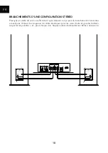
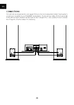
Page 20: ...connect your amplifier to your TRIANGLE loudspeakers You should use cables of the same length for the left and right channels and take special care to respect the and polarity for each channel Don t forget to strip the cables if it s necessary AUDIOIN CD AUX RECORDER PHONO SIGNAL GND AC IN AUDIOO UT PREO UT RECORDER ...

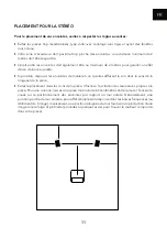
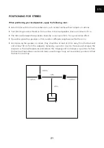
Page 21: ...2 m for a good stereo effect Î If possible place the speakers so that sound is diffused lengthwise within the room Î Avoid placing the speaker in corners they should be at least at 40 cm away from the back wall and at least 50 cm from the sidewalls Generally a position close to the rear wall increase the response in the low frequencies and reduce the imaging and contrariwise a position far from th...

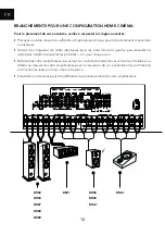
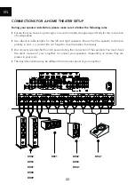
Page 22: ...or the left and right speakers Ensure that the speaker connection polarity and is correct Do not forget to strip the cables if necessary Î Disconnect your amplifier from AC power during the connection of the speakers You must check the user s manual of your amplifier to connect your speakers depending on where they are placed in your room Î The illustration below may be different from the rear pan...

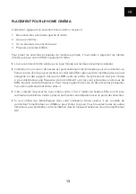
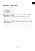
Page 23: ...cts channel featured on supports such as DVD audio or video The positioning of the subwoofer is not critical if you select a crossover frequency below 80 Hz Above this frequency it is better to move the subwoofer closer to the main speakers The best position being in between the two main speakers Ensure that it is not placed in the corner of the room to avoid creating unpleasant resonances Î We re...

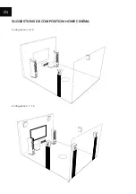
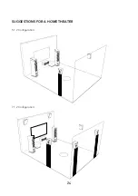
Page 24: ...24 SUGGESTIONS FOR A HOME THEATER 5 1 2 Configuration 7 1 2 Configuration ...

Page 25: ...25 ...

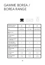
Page 26: ... KHz 90 22 57 22 51 22 Puissance admissible Power handling W RMS 80 100 80 Impédance minimale optimale Minimal Optimal impedance Ohms 4 5 8 5 3 8 3 6 8 Dimensions LxHxP mm inch 206 x 180 x 300 8 11 x 7 08 x 11 8 485 x 176 x 274 19 09 x 6 92 x 10 78 176 x 310 x 274 6 92 x 12 2 x 10 78 Poids de l enceinte Net weight 3 75 kg 8 26 lbs 7 52 kg 16 57 lbs 4 87 kg 10 7 lbs Poids avec packaging Gross weigh...

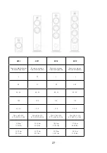
Page 27: ... 2 5 3 3 3 90 91 92 92 5 46 22 44 22 40 22 35 22 100 120 150 170 4 2 8 5 8 3 8 3 3 8 206 x 380 x 314 8 11 x 14 96 x 12 36 206 x 980 x 314 8 11 x 38 58 x 12 36 206 x 1020 x 314 8 11 x 40 15 x 12 36 206 x 1095 x 314 8 11 x 43 11 x 12 36 6 26 kg 13 22 lbs 16 92 kg 35 27 lbs 18 85 kg 41 55 lbs 21 8 kg 48 06 lbs 16 64 kg 35 27 lbs 23 05 kg 50 7 lbs 24 01 kg 52 91 lbs 26 1 kg 57 32 lbs ...

Page 28: ...gistrement en ligne Rien de plus simple vous pouvez vous enregistrer en deux clics à l adresse suivante https www trianglehifi com fr enregistrement GARANTIE WARRANTY Thanks for buying a TRIANGLE product We want you to enjoy your purchase to the fullest The first step is an easy registration of your products By doing this you will benefit from helpful tips products support special offers and 3 yea...

Page 29: ...ant de l intervention d une personne non habilitée par TRIANGLE Î Impacts sur l ébénisterie rayures écrasement chocs divers Note on the warranty Your TRIANGLE loudspeakers are warranted for 3 years This warranty takes effect from the date of purchase and covers any manufacturing defect or damage your loudspeakers could suffer as a result of these same defects This warranty is granted solely to the...

Page 30: ...mmagé de quelque manière que ce soit si le câble ou la prise d alimentation sont endommagés si un liquide ou un objet tombe sur cet appareil une exposition à la pluie ou à l humidité s il ne fonctionne pas correctement ou encore si l appareil chute SAFETY INSTRUCTIONS WARNING Read carefully all the safety instructions before using the device Î Keep these safety instructions for future references Î...

Page 31: ...www trianglehifi com SITE INTERNET WEBSITE facebook com trianglehifi instagram com trianglehifi f twitter com trianglehifi t I ...

Page 32: ... DESIGN BY TRIANGLE IN FRANCE Version 3 8 20201106 ...

Reviews: