SPSM
SP Series
Centrifugal Pumps
TriClover_Pump_SP_service_D400
Page 1: ...SPSM SP Series Centrifugal Pumps TriClover_Pump_SP_service_D400 ...
Page 2: ...ervice these pumps Failure to do so could result in personal injury or equipment damage SAFETY IMPORTANT SAFETY INFORMATION 3 INTRODUCTION GENERAL INFORMATION 4 INSTALLATION UNPACKING AND INSTALLATION 5 PIPING HINTS 8 MAINTENANCE CLEANING 9 SEAL SERVICING 10 TYPE D OR F SEALS EXTERNAL BALANCED 11 TYPE A AND B PACKING GLAND SEAL 15 TYPE E WATER COOLED BALANCED DOUBLE SEAL 16 FINAL ASSEMBLY 17 PUMP ...
Page 3: ...ould result in death or serious injury Safety is very important DO NOT attempt to modify any Tri Clover product To do so could create unsafe conditions and void all warranties DO NOT place any Tri Clover product in an application where general product service ratings are exceeded The following DANGER WARNING AND CAUTION signs and their meanings are used within these instructions IMPORTANT SAFETY I...
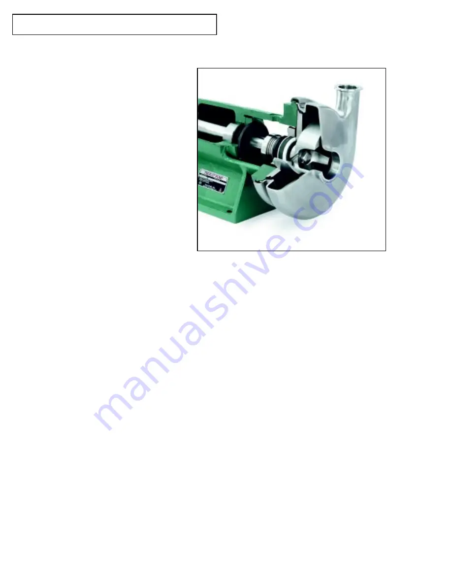
Page 4: ...r to the pump and the liquid end or pump section The pump impeller is mounted to the power frame shaft and is secured by a floating retainer or by a threaded shaft and castellated nut The casing is clamped to the power frame greatly simplifying removal and permitting positioning of the discharge outlet through 360 Three basic standard seal designs external balanced seal packing gland and water coo...
Page 5: ...tall the oiler 1 Screw the pipe nipple into the adapter after applying thread compound to the threads on the nipple 2 Using a spirit level check the pipe nipple to make sure it is level as oil will not flow unless the oiler is level 3 Install the oiler on the nipple with the bottle up 4 Remove the oiler bottle fill it with oil invert the bottle and assemble it to the lower oiler reservoir Allow th...
Page 6: ...ap of 3 4 to 11 2 between the bottom of the base plate and the top of the foundation should be allowed for grouting Adjust the metal blocks or wedges until the pump and motor shafts are level Use a level to check the coupling halves and suction inlet for vertical and horizontal alignment The nuts on the foundation bolts should then be turned down until they are finger tight FLEXIBLE COUPLINGS A fl...
Page 7: ...nt procedures have been completed the foundation bolts should be evenly tightened but not too firmly The unit can then be grouted to the foundation A form should be constructed around the base plate to hold the grout The base plate should be completely filled with grout and it may be desirable to grout the support blocks or wedges in place Do not tighten the foundation bolts until the grout has ha...
Page 8: ...n inlet should be increased in size An eccentric tapered reducer should be used in lieu of a straight concentric tapered reducer to prevent air pockets from forming and impairing pump efficiency In turn the eccentric reducer may be placed at the inlet of the pump and should be positioned so the straight side is up A horizontal suction pipe must have a gradual rise to the pump A high point in the s...
Page 9: ...ion and discharge piping 2 Turn the wingnut on the clamp assembly until tension on the clamp saddle is relieved 3 Open the saddle and remove the casing 4 On pumps with the floating impeller retainer a Rotate the impeller until the retainer is in a horizontal position b Push back on the impeller and center the retainer in the shaft c Slide the impeller forward and remove it 5 On pumps with threaded...
Page 10: ...t and impeller Threaded Shaft Models 1 Remove the cotter pin and turn the castellated nut in a counterclockwise direction 2 Remove the washer s and impeller REASSEMBLY Floating Retainer Pin Models 1 Rotate the shaft until the retainer pin hole is horizontal Insert the retainer center it in the shaft and slide the impeller on 2 Hold the impeller tight against the shoulder on the shaft and rotate it...
Page 11: ...at prevents fluid leakage from the rear of the seal Torque is transmitted by tabs on the seal cup that engage slots on the seal periphery and by another slot that engages a lug on the drive collar The seal should be replaced when the clearance between the carbon seal face and the stationary seal surface is less than 1 32 or when leakage is observed DISASSEMBLY 1 Disconnect piping 2 Remove the casi...
Page 12: ...ew heads If the seal has been replaced or the drive collar loosened it will need to be repositioned Two methods are available EXTERNAL BALANCED SEALS SETTING SEAL DRIVE COLLAR BY MEASUREMENT 1 Install the backplate gasket and casing 2 Install and tighten casing clamp 3 At a location behind the backplate scribe a mark on the shaft See Figure Six or Figure Seven 4 Remove casing clamp casing and back...
Page 13: ...e backplate and casing 4 Install and tighten the casing clamp 5 Slide the drive collar and seal assembly toward the backplate until the nose of the drive collar pushes the o ring and carbon seal tight against the backplate 6 Slide the drive collar away from the backplate 1 32 and secure the drive collar in this location with the setscrews When the drive collar is properly positioned and seal compo...
Page 14: ...Tri Clover are in a package The first ring of the packing is tagged and the remainder of the rings are to be installed as they are assembled in the package The packing rings should be twisted laterally until they slide over the shaft The joints in the packing rings should be staggered to minimize leakage 4 Replace the split gland and nuts 5 Tighten the split gland nuts only until a slight drag is ...
Page 15: ...g type of packing REASSEMBLY Assemble the packing rings in the stuffing box portion of the backplate making sure the ring joints are staggered Note The packing rings are accurately die formed and must be handled carefully Slide the backplate onto the shaft being careful not to damage the packing rings Assemble the split gland to the backplate tightening the nuts only until there is a slight drag o...
Page 16: ...g clamp casing impeller and casing gasket 5 Carefully slide the backplate assembly forward off the pump 6 The seal rotating components will now be accessible The seal drive collar can be removed by loosening two set screws 7 All seal parts then can be removed by sliding them forward off the shaft INSPECTION Examine the seal rotating and stationary sealing surfaces for nicks scratches or other dama...
Page 17: ...e drive collar 9 Slide the two seals toward each other so that the spring nests in the cups 10 Assemble the stuffing box to the backplate verifying that the o ring is in place in the groove in the front flange 11 Carefully position the backplate and the stuffing box over the seal assembly 12 Position the backplate in the recess in the bearing frame and hold in place 13 Move the follower forward an...
Page 18: ...the lubrication fittings are wiped clean before greasing to prevent dirt from being forced into the bearings during greasing If your pump has been operated under extremely dusty or wet conditions for several months or has been idle for a long period of time the bearings should be cleaned thoroughly with nonflammable solvent and new grease applied Refer to the applicable paragraphs for disassembly ...
Page 19: ...e the damaged bearing s from the shaft 4 If grease seals need replacement press or drive them out of the bearing covers INSPECTION 1 Remove the drain plug from the power frame If your pump is equipped with an oiler and it is desirable to drain the power frame reservoir remove the oiler from the power frame 2 Remove any accumulation of grease from the inside of the power frame 3 Reassemble the drai...
Page 20: ... the shaft being careful not to damage the grease seal 7 Start the bearings in their bores and tap the shaft firmly with a soft hammer until the bearings are firmly seated 8 Install shims between the outboard bearing cap and the power frame Refer to figure ten Assemble the inboard and outboard bearing covers to the power frame 9 Lubricate the bearings using approximately 1 2 ounce of recommended g...
Page 21: ...Have motor serviced or replaced d Power frame shaft is bent d Replace shaft or worn e Power frame bearings e Replace bearings are worn f Packings are too tight f Loosen packing gland replace packing if required g Excessive misalignment g Align pump and driver betwenn pump and driver TROUBLESHOOTING Tri Clover pumps are relatively maintenance free with the exception of sanitizing and lubrication Li...
Page 22: ...salignment h See 3 g on previous page between pump and driver i Cavitation i See note on previous page 5 Excessive a Pump is not leveled properly a Level pump vibration b Excessive misalignment b See 3 g on previous page c Impeller is damaged c Replace impeller d Piping is not supported d Support discharge and suction piping e Power frame shaft is bent e See 3 d on previous page or worn f Cavitati...
Page 23: ...eller 1 24B Cotter Pin Impeller 1 29 Seal Cage 1 35 Bearing Cover Inboard 1 37 Bearing Cover Outboard 1 37A Bearing Cover Screw 8 44 Grease Fitting 2 46 Coupling key 1 KEY DESCRIPTION QTY 47 Bearing Seal Inboard 1 49 Bearing Seal Outboard 1 69 Lockwasher 1 71A Adapter Pin External Seal 1 75 Clamp Assembly Complete 1 77 Elbow 2 80 Carbon Seal E Seal Takes 2 1 80A Cup 1 80B O ring Seal E Seal Takes ...
Page 24: ...80C 85 37A 47 35 16 44 2 24 6 19B 131 92 18 22 69 92 37 49 37A Type E Water Cooled Balanced Double Seal 17G 17F 17H 80 80B 80F 80I 80H 80G 80F 80B 80 83 83A 83B 11G SP Series Pump with Floating Retainer Threaded Shaft and Castellated Nut Retainer System for Use with Type D F or E Seals 6B 24B 44 17 Optional Power Frame Oiler Additional Type DG Clamped in Seal Seat Components For use with type D se...
Page 25: ...6 P438 16 P438 16 P438 1 17 Split Gland 2 required P214A 17C 1 316 P326A 17C 1 316 P438A 17C 1 316 P438A 17C 1 316 P438A 17C 17A Nut Split Gland NU1100H SS NU1300H SS NU1300H SS NU1300H SS NU1300H 17B Stud Split Gland SP114 82 S SP216 82 S P326A 17D S P326A 17D S P326A 17 17F Follower E Balanced 114E 17A 316 216E 17A 316 328E 17 316 328E 17 316 328E 17 3 17G Machine Screw SC1106E SS SC1308H SS SC1...
Page 26: ...G Seal Seat TC SP114G 80 1 1 TC SP216G 80 1 1 TC SP328G 80 1 1 TC SP328G 80 1 1 TC SP328G 80 1 Type DG Seal Seat Ceramic SP114G 80 1 1 CER SP216G 80 1 1 CER SP328G 80 1 1 CER SP328G 80 1 1 CER SP328G 80 1 1 Type DG Seal Seat SC SP114G 80 1 1 SC SP216G 80 1 1 SC SP328G 80 1 1 SC SP328 80 1 1 SC SP328G 80 1 80P Gasket Outboard PTFE SP114G 80 1 2 G SP216G 80 1 2 G SP328G 80 1 2 G SP328G 80 1 2 G SP32...
Page 27: ... any implied warranty of merchantability or fitness for a particu lar purpose All claims must be in writing and must be mailed or delivered by purchaser within thirty 30 days after purchaser learns of the facts upon which such claim is based Any claim not made in writing and within the time period specified above shall be deemed waived Purchaser s sole and exclusive remedy and Tri Clover Inc s max...