Series 91000
Self-Operating Temperature Regulators
Operation, Installation & Maintenance Manual
Indicating and Non-indicating
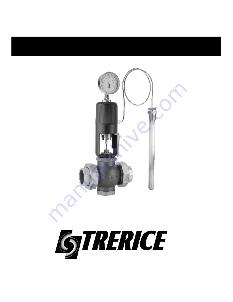
Model 91400 Shown
Instruction Manual
IH-2
Page 1: ...Series 91000 Self Operating Temperature Regulators Operation Installation Maintenance Manual Indicating and Non indicating Model 91400 Shown Instruction Manual IH 2...
Page 2: ...Action 10 11 Valve Body Assembly 12 13 Reversing the Valve Action 14 15 3 Way Regulator Installation Maintenance 16 Model 91600 Safety Type Installation Maintenance 17 Typical Applications 18 19 Typic...
Page 3: ...65 F 5 to 20 C N A 30 to 115 F C R02 40 to 90 F 5 to 30 C 65 to 85 F 20 to 30 C N A 50 to 140 F C R03 30 to 115 F 0 to 45 C 85 to 110 F 30 to 45 C 50 to 80 F 10 to 25 C 30 to 115 F C R04 50 to 140 F...
Page 4: ...ture sensing bulbs on a regulator are not recommended for direct insertion into any pressurized system The use of a Thermowell is strongly encouraged Brass and Steel Thermowells are rated to 500 PSIG...
Page 5: ...moval for service Blow out all pipe lines thoroughly to eliminate all foreign material from the system Pipe thread compound should be applied only on external or male pipe threads not on the union nut...
Page 6: ...s this may require a small by pass flow line around the valve to maintain representative system temperatures at the sensing bulb SENSING BULB INSTALLATION To install a union connected sensing bulb rem...
Page 7: ...HE SMALL HEX STEM JAM NUTS THIS IS A CRITICAL SETTING FOR THE PROPER SEATING STROKE OF THE REGULATOR PLACING THE REGULATOR INTO OPERATION AND SETTING THE CONTROL POINT Figure 1 Model 91000 shown CAUTI...
Page 8: ...nal drop of oil on the stem will aid in eliminating mineral deposits and maintaining a free running stem for accurate regulation See Figure Figure 2 Removing any sharp mineral crystals from the stem w...
Page 9: ...Remove all accumulations of mineral deposits or other debris before re building A 4375 diameter reamer is ideal to remove deposits from the bonnet if the bonnet is removed from the body A 45 diameter...
Page 10: ...completely off of and below the scale then the thermal system is most likely dead and needs to be replaced On all other model of actuators 1 Record the current adjusting screw setting relative to the...
Page 11: ...up There should be at least 1 4 of motion 3 If no motion is seen the valve is jammed A Remove valve from line and inspect for debris caught between the valve seat and the valve plug preventing the val...
Page 12: ...D POLISHED PORTION OF THE VALVE STEM 5 Remove the Bonnet Nut holding the actuator to the valve with a 11 2 wrench 6 Unscrew the valve stem from the actuator stem by turning the entire valve body If th...
Page 13: ...screw in up to reference number 8 5 Place valve stem up through the Yoke and Bonnet Nut 6 Thread the valve stem into the actuator stem A Use a 5 16 wrench to hold or turn the actuator stem B Use a 3...
Page 14: ...gulator these valves are used for HEATING Stem Out To Close valves close with temperature decrease and outward stem motion On a regulator these valves are used for COOLING 1 2 through 2 Bronze Body va...
Page 15: ...Thread the stem in until the cross pin holes in the stem and the valve plug are centered upon each other B Check the centering by making an extra 1 2 turn to see if this improves the centering If not...
Page 16: ...ses as temperature increases Port A is the common port and remains open G LOWER PORT B UPPER PORT C COMMON PORT A F E for Mixing or Diverting MIXING FLOW DIAGRAM DIVERTING FLOW DIAGRAM TEMPERATURE COL...
Page 17: ...Report basis and the regulator will be thoroughly inspected and tested Model 91600 SPECIAL INSTRUCTIONS 91600 Stem The actuator stem in a Model 91600 actuator does not turn When removing or attaching...
Page 18: ...on Using a Self Op 3 Way Diverting Valve Typical Plumbing for a Self Op 3 Way Mixing Valve HEATING Connect Upper Port C to Water Glycol Return and Lower Port B to Heat Exchanger COOLING Connect Upper...
Page 19: ...UEL OIL STORAGE TANK PUMP Teflon covered sensor and tubing Sensor attached into tank with pipe hangers STEAM COILS HEAT EXCHANGER Influence Side Process Side STEAM RETURN TO TRAP THEN BOILER STEAM RET...
Page 20: ...e average temperature location or add agitation 3 Tube system assembly has lost 3 Replace the thermal actuator pressure fill 4 Stem adjustment too short 4 Readjust See Figure 6 Closes with temperature...
Page 21: ...sure too low 5 Increase supply pressure 6 Heat exchanger not large enough 6 Replace with proper capacity 7 Faulty or undersized steam trap 7 Install trap of proper capacity 8 Stem moves into body to o...
Page 22: ...Page 22 Notes Adjustments Stem Dimensions Maintenance Logs...
Page 23: ...Page 23 Notes Adjustments Stem Dimensions Maintenance Logs...
Page 24: ...ustomer Service and International Sales 12950 W Eight Mile Road Oak Park Michigan 48237 Toll Free 1 888 873 7423 Fax 1 248 399 7246 www TRERICE com Regional Sales Offices Northeast Central East Midwes...