


XO-1
•
21
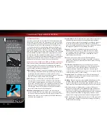
Use stiffer springs to reduce bottoming out the chassis, reduce
body lean, control brake dive, and provide a firmer, more
responsive feel. Increasing the spring rate will increase the
responsiveness of the suspension. This may be beneficial in some
conditions, but may make the car feel twitchy or ‘nervous’ in
others. Decreasing spring rate decreases the responsiveness of the
suspension, making it easier to drive. When changing springs on
the model it should not be necessary to re-adjust the spring pre-
load. The accessory springs have been designed so the ride height
should be the same before and after changing springs.
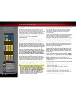
Optional springs available from Traxxas are listed below. Refer
to your parts list for a complete part number listing. Higher rate
springs are stiffer. Springs can be identified by stripes of color on
one end.
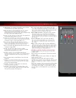
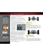
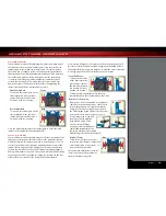
Ride Height
Ride height can be adjusted by turning the spring pre-load adjusters
on the shock bodies. Turn the adjusters to the left to raise the ride
height. Turn them to the right to lower the ride height. When adjusting
spring pre-load, be sure to change the adjustment equally on the left
and right sides so the suspension remains balanced. Optimum ride
height is 15mm clearance between the front of the chassis and the
ground, and 18mm between the rear of the chassis and the ground.
Always set the ride height so the chassis has a slight forward rake, with
the rear ride height slightly higher than the front ride height.
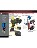
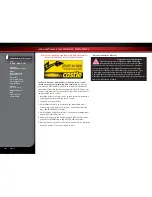
Lower Shock Mounting Positions
In the out-of-the-box configuration, the shocks are installed in the
furthest hole out on the front and rear suspension arms. It is not
recommended to alter the shock position on the control arm.
The shocks have been internally limited (front only) and spring
rates chosen to work perfectly with the hole position in the
suspension arm.
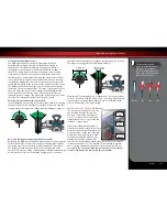
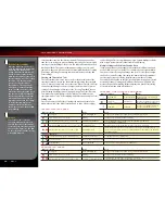
Upper Shock Mounting Positions
The upper shock mounting
positions can be used to
provide small changes in the
suspension stiffness when
changing spring rates is too
drastic of a change. Placing
the upper shock mount
inwards on the shock tower
one hole will soften the
suspension slightly. Be careful
to recheck your ride height as
this adjustment will change
the ride height of the vehicle.
Shock Oil
The 4 oil-filled shocks (dampers) effectively control the suspension
movement by preventing the wheels and tires from continuing to
“bounce” after rebounding from a bump. Changing the oil in the
shocks can vary the suspension damping effect. Changing the oil to
a higher viscosity oil will increase damping. Lowering the viscosity
of the oil will cause the suspension damping to be reduced.
Damping should be increased (with higher viscosity oil) if the model
is bottoming easily over rougher surfaces. Damping should be
decreased (with thinner viscosity oil) if the model is hopping over
small bumps and feels unstable. The viscosity of shock oil is affected
by extremes in operating temperature; an oil of certain viscosity will
become less viscous at higher temperatures and more viscous at
lower temperatures. Operating in regions with cold temperatures
may require lower viscosity oil.
From the factory, the shocks are filled with SAE-80W silicone oil.
Only use 100% silicone oil in the shock.
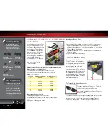
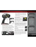
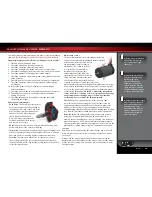
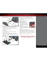
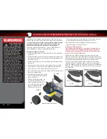
Replacing Shock Oil
For easier service, the shocks should be
removed from the vehicle and disassembled
to change the oil.
1. Remove the lower spring retainer and
shock spring.
2. Remove the upper shock cap using the
shock wrench and suspension multi tool.
BASIC TUNING ADJUSTMENTS
Stock
OK
Limits Down Travel
(
Not preferred)
Do Not Use
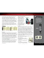
Optional Springs
Stripe Color
Spring Rate
Stripe Color
Spring Rate
Double Pink
1.4 N/mm (8.0 lb/in)
White
2.9 N/mm (16.6 lb/in)
Double Blue
1.6 N/mm (9.1 lb/in)
Orange
3.2 N/mm (18.3 lb/in)
Double Green
1.8 N/mm (10.3 lb/in)
Green
3.5 N/mm (20 lb/in)
Double Black
2.0 N/mm (11.4 lb/in)
Gold
3.8 N/mm (21.7 lb/in)
Double Purple
2.3 N/mm (13.1 lb/in)
Tan
4.1 N/mm (23.4 lb/in)
Yellow
2.6 N/mm (14.8 lb/in)
Black
4.4 N/mm (25.1 lb/in)
All above springs are red springs. Stock springs are 1.6 N/mm white springs.
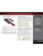
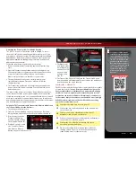
Important:
The shocks are
assembled at the factory
with a center-to-center
distance (between the rod
end balls) of 87mm front
and 83mm rear. Any time
the shocks are removed and
disassembled, this distance
should be checked to ensure
proper operation of the
suspension.
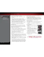
Shock Piston Sizes
1.4
1.4
1.4
1.3
1.3
1.3
1.4mm
(Stock)
1.3mm
83mm front
87mm rear


