SETTING THE IDLE SPEED
Now that the engine mixture is tuned, the idle speed may be
set too high. Only set the idle speed when the engine is at its nor-
mal operating temperature. Adjust the throttle trim on the transmit-
ter so that the brake on the truck is applied. Next, reset the idle
speed by removing the air filter and adjusting the idle speed screw
on the side of the carburetor (see drawing on page 5). Turn the
screw out (counter-clockwise) to reduce the idle. Re-adjust the
throttle trim on the transmitter as necessary (so that the brake is
no longer applied). The idle should be set slow enough that the
truck does not try to move at idle.
ADJUSTMENTS
• TOE IN
Geometry and alignment specs play an important roll in your
truck’s handling, so take the time to set them correctly. Set the
steering trim on your transmitter to neutral. Now, adjust your tie
rods so that both wheels are pointing straight ahead and are par-
allel to each other (0 degrees toe in). This will ensure the same
amount of steering in both directions. If you run out of adjust-
ment, then the steering servo will have to be re-centered (see
“centering your servos on page 9).
For increased stability add
1-2 degrees of toe in to each front wheel. Use the turnbuck-
les to adjust the alignment.
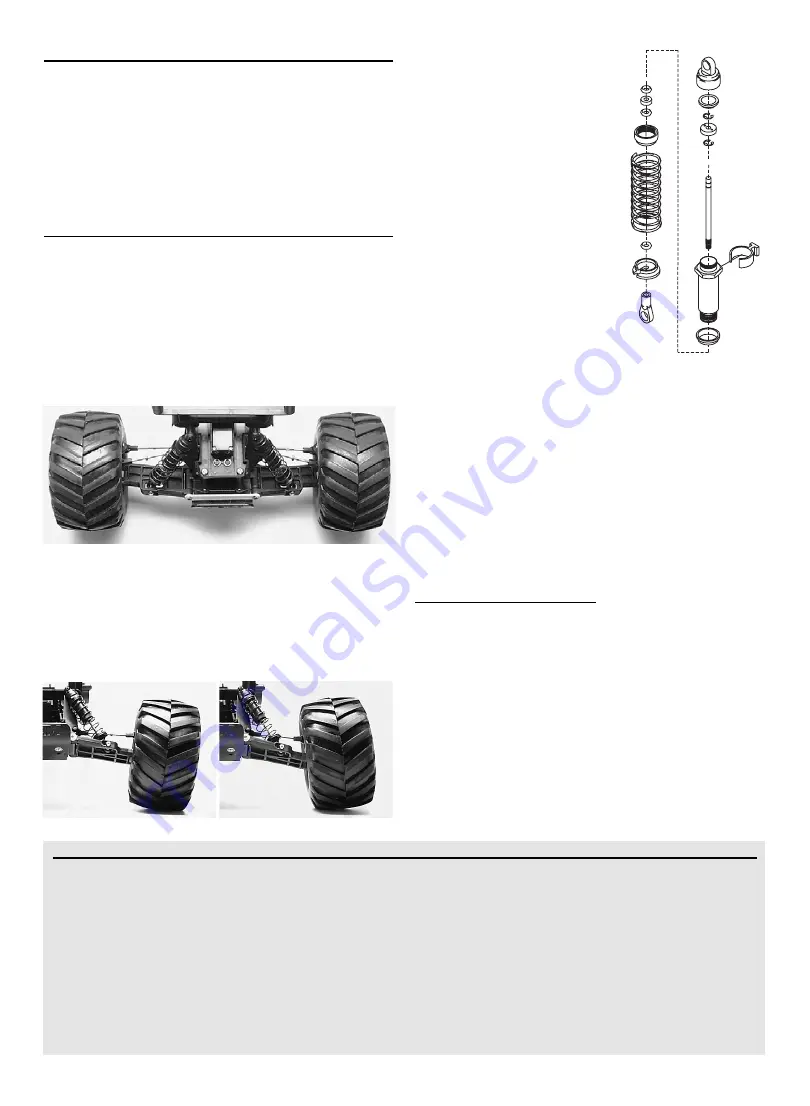
• CAMBER
The camber angle of both the front and rear wheels can be
adjusted with the camber rods (upper turnbuckles). Use a square
or right-angle triangle to set the camber accurately. Adjust the
front wheels to 0 degrees of camber (wheel perpendicular to the
ground). In the rear, adjust the wheels to 1 to 2 degrees of nega-
tive camber. These adjustments should be set with the truck
positioned at its normal ride height.
• SHOCKS
The four shocks on Nitro Stampede
have the most influence on its han-
dling. Whenever you rebuild your
shocks, or make any changes to the
pistons, springs or oil, always do it
carefully and in pairs (front or rear).
Piston head selection depends on the
range of oil viscosities that you have
available. For example, using a two-
hole piston with a lightweight oil will, at
one point, give you the same dampen-
ing as a three-hole piston with heavier
oil. We recommend using the two-hole
pistons with a range of oil viscosities
from 10W to 50W (available from your
hobby shop). The thinner viscosity oils
(30W or less) flow more smoothly and
are more consistent, while thicker oils
provide more dampening.
Use only
100% pure silicone shock oil to
prolong seal life.
The ride height for Nitro Stampede can be adjusted by adding
or removing the clip-on spring pre-load spacers. Instead of
adding spacers to increase stiffness, use stiffer springs. Adjust
the ride height so that the suspension arms are slightly above
being parallel to the ground. Observe how Nitro Stampede han-
dles in turns. If it is picking up the inside rear wheel in hard turns,
then stiffen the
front
suspension. If it picking up the inside front
wheel in hard turns, then stiffen the
rear
suspension. Proper set-
up will add stability and help prevent roll-overs.
• GEAR RATIOS
A unique Nitro Stampede feature is the ability to change the
gear ratios. The final drive ratio of the gearbox is 3.75 to 1. Use
the following formula to calculate the overall ratio:
Number of
Spur
gear teeth
Number of
Clutch bell
gear teeth
x 3.75
Final drive ratio
Nitro Stampede comes with a 66-tooth spur gear and an 18-
tooth pinion (clutch bell) gear. This combination will provide the
best overall acceleration and top speed. If you want more accel-
eration and less top speed, then use a smaller clutch bell gear
(fewer teeth). For more top speed, use a larger clutch bell gear.
• ADJUSTING THE SLIPPER CLUTCH
The Nitro Stampede is equipped with an adjustable slipper
clutch which is built into the large spur gear. The purpose of the
slipper clutch is to regulate the amount of power sent to the rear
wheels in order to prevent rear tire spin. It also reduces the
shock transferred to the drive components when the truck is
jumped. When it slips, the slipper clutch makes a high-pitch
chirping noise, which you may be able to hear over the engine
PRE-LOAD
SPACERS
MAINTENANCE
1) Check the wheels and steering for binding. Check the operation
of the shock absorbers.
2) Check the wiring for any frayed wires or loose connections,
including the wires on the EZ-Start quick connector. Fraying
or melting of the blue wire on your EZ Start system can
cause your glow plugs to immediately short out.
3) Check the tightness of the grub screws in the collars on the
throttle and steering linkages.
4) Check the air filter for proper mounting and filtration.
5) Check the mounting of the receiver and servos.
6) Check the tightness of the wheel nuts with a wrench.
7) Check the fuel tank and all hoses for signs of leaks.
8) Check the operation of the radio system, especially the
condition of the batteries.
9) Check the exhaust system for leaks, cracks, or tears. Do not
run the model if there are any exhaust leaks.
10) Use Traxxas Nitro Wash spray cleaner to keep the model
clean of accumulated dirt and oil. Do not spray any radio
components with Nitro Wash. Do not spray Nitro Wash into
a dirty air filter while it is installed on the engine.
11) The steering servo saver will wear out over time. If the
steering becomes loose, the servo saver should be replaced.
Positive camber
Negative camber
Zero degrees of toe-in
Contact Traxxas for assistance: 1-888-TRAXXAS.
972-265-8000
(outside USA). E-Mail us at
8


