background image

12

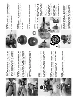
STEP 7:

Remove the 3x23mm cap-head machine 

screws that fasten the header to the


engine. Carefully remove the header to 

avoid damaging the gasket.

To separate the engine from the engine 

mount, remove the four 3x8mm cap-head 

machine screws. 

Rebuilding the Engine

STEP 1:

Remove the 4mm locknut from the front 

pipe hanger. Pull the pipe from the rear 

exhaust header.

STEP 2:

Unplug 

the blue wire 

from the 

glow plug. Remove 

the 

fuel line from the carburetor inlet and from the exhaust 

header pressure fitting. Disconnect the red and black 

wires from the EZ-Start

®

 motor.

STEP 3:


Remove the EZ-Start gearbox by removing the three 

3x8mm round-head machine screws.

STEP 4:

Use a 2.5mm hex driver to remove the yellow ground 

wire from the engine mount. Move the EZ-Start 

wiring 

harness out of the way.

STEP 5:

Use a 2.5mm hex driver to remove the three


remaining 3x10mm cap-head machine screws from


the engine mount.

STEP 6:

Pull the engine from the chassis. Turn the engine 


so that the throttle linkage to the carburetor will 


come out. 

STEP 9: Changing the piston and sleeve assembly

Use a 5/16 inch nut driver to remove the glow plug and 

copper gasket. 

STEP 10:

Use a 2.5mm allen wrench to remove the four 3x12mm 

cap-head screws that fasten the cylinder head. Rock 

the cylinder head gently from side 

to side 

to release 

it 

from the sleeve. Note the thin aluminum head gaskets. 

We recommend that you replace these gaskets with 

new ones upon reassembly.

STEP 11:

Remove the backplate and the


starter shaft. Replace the backplate 

gasket with a new one during


assembly.

STEP 12: 

The piston and sleeve are a matched set. When the 

piston and sleeve are disassembled, they must be 

reassembled in the same orientation. Use a hobby 

knife to scratch a mark to indicate the location of the 

piston in relation to the pinning of the sleeve. 

STEP 8:

Removing the carburetor is not necessary to rebuild 

the engine, unless you intend to replace the internal 

bearings 

of 

the 

engine. 

Remove 

the 

carburetor 

by 

loosening the 3mm locknut and pulling the carburetor 

straight up. 

Summary of Contents for Nitro Sport 4510

Page 1: ...OPERATING INSTRUCTIONS COVERS MODEL 4510 KC1149 R01 Rev 090806...

Page 2: ...lt in property damage and serious injury You alone must see to it that the instructions are followed and the precautions are adhered to The Nitro Sport is not intended for use by children without the...

Page 3: ...for nickel cadmium The original rechargeable hobby pack NiCad batteries have very high current handling high capacity and can last up to 1000 charging cycles Good charging procedures are required to...

Page 4: ...ur frequency Therearesixdifferentchannelsnumbered1through6 Eachofthesixchannelsisrepresentedbyacolor Lookatthecrystal inthebackofthetransmittertodeterminewhichofthechannels yourtruckisoperating Cleari...

Page 5: ...he best performing engine Make sure you are using a good quality battery pack that is fully charged new batteries usually require several charge cycles to reach peak voltage and full capacity This is...

Page 6: ...f the ground BREAKING IN THE ENGINE VERY IMPORTANT Once your engine is running it must be broken in The key to breaking in your engine is patience The break in time will take about 1 to 1 hours During...

Page 7: ...make several more high speed runs and retest 7 When the low speed needle is set correctly the engine s throttle response should be very quick Idle Speed Adjustment Once the high and low speed mixture...

Page 8: ...nique Nitro Sport feature is the ability to change the gear ratios The final drive ratio of the gearbox is 2 81 to 1 Use the following formula to calculate the overall ratio Nitro Sport comes with a 7...

Page 9: ...the crystal Connect the red and black cable from the battery holder to the batt terminal on the receiver The red wire is positive and the black wire is negative Place fresh AA batteries in the transmi...

Page 10: ...xas makes three glow plugs The standard hot plug part 3230 is the stock replacement plug for Pro 15 engines The optional heavy duty part 3231 and super duty part 3232 plugs will last longer in most ca...

Page 11: ...ure is too lean Richen the high speed mixture page 7 24 Idle speed set too low Increase idle speed page 7 25 Fuel flow blocked Check that all fuel lines are clear with no pin hole leaks Check for dirt...

Page 12: ...he engine from the chassis Turn the engine so that the throttle linkage to the carburetor will come out STEP 9 Changing the piston and sleeve assembly Use a 5 16 inch nut driver to remove the glow plu...

Page 13: ...t pin also Rinse thoroughly with denatured alcohol and lube with after run oil STEP 13 Pull the sleeve straight up and out of the crankcase If the sleeve will not move rotate the crankshaft until the...

Page 14: ...14 STEP 25 To assemble the connecting rod and piston place a drop of castor oil in the top end of the connecting rod Insert the wrist pin through the piston and the top of the connecting rod Secure t...

Page 15: ......

Reviews: