background image

22 • TRAXXAS

TUNING ADJUSTMENTS

MOTOR AND GEARING

Extensive testing has been done to determine the best gear ratio 
for your model. The stock gearing balances power, speed, and 
efficiency to optimize the performance of the model. However, 
you may wish to try different gear ratios in order to customize the 
performance of your model. The gearing chart on this page shows 
appropriate gearing for the model. 

 
By installing a pinion with fewer teeth, or a spur gear with 
more teeth, the transmission’s final drive ratio is increased. 
This means greater rpm is required to achieve a given speed. 
Using a numerically higher gear ratio will increase torque, but 
reduce top speed. Installing a pinion with more teeth, or a spur 
gear with fewer teeth, will decrease the final drive ratio, which 
will generally increase top speed but reduce torque. However, 
installing too large a pinion will “overgear” the model, which will 
reduce performance and may overheat the motor and speed 
control. Use the following formula to calculate the overall ratio for 
combinations not listed on the gear chart:

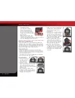
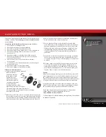
Motor Installation

To access the motor, 
remove the gear cover 
by removing the single 
screw on the top of the 
gear cover. The motor 
uses an aluminum 
mount for quick, easy 
motor access and 
gearing adjustment. To 
remove the motor, first 
open the right battery 
door and slide out the ESC. Next, remove the single large hex screw 
using the supplied 2.5mm wrench.  Then rotate the motor and 
mount to the side of the model, and slide backward off the post.

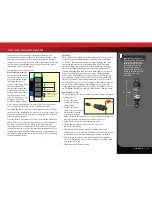
Pinion Gear Installation Instructions

1.  Remove the motor as described  

previously in Motor Installation

2.  Use a 1.5mm wrench to loosen the 

pinion’s set screw. Remove the pinion. 

3.  Place the replacement pinion gear onto 

the motor shaft. Align the set screw 
hole with the flat side of the shaft. 

4.  Thread a 1.5mm set screw into the 

pinion gear but do not tighten it yet. 

5.  Slide the pinion gear down the motor shaft so the wrench shaft 

fits into the notch in the motor mount, as shown. Tighten the 
set screw. 

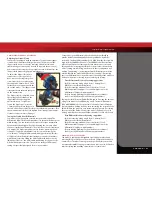
Adjusting Gear Mesh

Incorrect gear mesh is the most common 
cause of stripped spur gears. Gear mesh 
should be checked and adjusted anytime 
a gear is replaced. Access the gears by 
removing the single screw on the top  
gear cover. 

To set the gear mesh, cut a narrow strip of 
notebook paper and run it into the gear 
mesh of the motor. The motor is mounted 
to an aluminum motor mount. Loosen 
the single motor mount screw with the 
provided 2.5mm wrench to slide the motor 
mount. Slide the motor and pinion gear into 
the spur gear. Retighten the motor mount 
screw and then remove the strip of paper. 
You should be able to run a fresh strip of 
paper through the gears without binding 
them. Gear mesh can be checked visually by 
removing the gear viewing port cover. 

Motor Mount 

Screw

Do Not Loosen

# Spur Gear Teeth

x 5.04 = Final Gear Ratio

# Pinion Gear Teeth

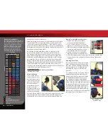
Gearing Compatibility Chart

The chart on the left shows a full range of 
gear combinations. The stock ratio for is 
shown in green. The gear combinations 
in red are not suitable when using the 
included 6-cell battery, speed control 
and motor. These gear combinations 
have been included in this chart as 
they may be used with certain other 
aftermarket equipment combinations. 

Spur Gear

Pinion Gear

45

50

55

16

-

-

17.33

17

-

-

16.31

18

-

-

15.40

19

-

-

14.59

20

-

-

13.86

21

-

-

13.20

22

-

11.45

12.60

23

-

10.96

12.05

24

-

10.50

11.55

25

-

10.08

11.09

26

8.72

9.69

10.66

27

8.40

9.33

10.27

28

8.10

9.00

9.90

29

7.82

8.69

9.56

30

7.56

8.40

9.24

31

7.32

8.13

8.94

32

7.09

7.88

8.66

33

6.87

7.64

8.40

34

6.67

7.41

8.15

35

6.48

7.20

7.92

36

6.30

7.00

-

37

6.13

6.81

-

38

5.97

6.63

-

39

5.82

6.46

-

40

5.67

6.30

-

41

5.53

-

-

42

5.40

-

-

43

5.27

-

-

44

5.15

-

-

45

5.04

-

-

46

-

-

-

   Stock

   Requires aftermarket 540 motor to fit

   Usable range

   Not recommended with stock ESC, motor and batteries

   Dual batteries with parallel connector only

   Does not fit

Gear Viewing Port  

Cover Removal

Summary of Contents for Boss 302 7303

Page 1: ...MODEL 7305 owner s manual...

Page 2: ...possible Traxxas models are about experiencing total performance and satisfaction not just with your model but also with the company that stands behind it We know you re excited about getting your ne...

Page 3: ...raxxas com You may also e mail customer support with your question at support Traxxas com Join thousands of registered members in our online community at Traxxas com Traxxas offers a full service on s...

Page 4: ...attery Traxxas strongly encourages you to recycle your Power Cell battery when it has reached the end of its useful life Do not throw your battery in the trash All Power Cell battery packs display the...

Page 5: ...is will prevent air bubbles Placing both ends of the decal down and then trying to smooth it out will result in air pockets Look at the photos on the box for typical decal placement TIRE GLUING The fa...

Page 6: ...y Mount Hex Hub Rear Suspension Arm Axle Carrier Pivot Ball Toe Link Light Pipe Receiver Box Steering Servo Front Body Mount Battery Compartment Door Battery Compartment Vent Electronic Speed Control...

Page 7: ...radio system See page 13 Fully charge the battery pack included with your model Follow this procedure to make sure your radio system works properly at a distance and that there is no interference fro...

Page 8: ...2 5 Wiring Diagram MOTOR MOTOR TQ TRANSMITTER Antenna Steering Trim Throttle Trim Throttle Trigger Throttle Neutral Adjust Steering Wheel Power Switch Battery Compartment Servo Reversing Switch Power...

Page 9: ...ses mAh Abbreviation for milliamp hour A measure of the capacity of the battery pack The higher the number the longer the battery will last between recharges Neutral position The standing position tha...

Page 10: ...charged batteries The power indicator light does not indicate the charge level of the battery pack installed in the model SETTING UP THE ANTENNA 1 Locate the black antenna wire that exits the receive...

Page 11: ...external low voltage detector sold separately consult your hobby dealer THE TRAXXAS HIGH CURRENT CONNECTOR Your model is equipped with the Traxxas High Current Connector Standard connectors restrict...

Page 12: ...he electronic speed control This control has been preset for you at the factory Electronic Steering Trim The electronic steering trim located on the face of the transmitter adjusts the neutral center...

Page 13: ...model the front wheels should be pointing straight ahead If the wheels are turned slightly to the left or right slowly adjust the steering trim control on the transmitter until they are pointing stra...

Page 14: ...d fingers are clear of the wheels 1 With the transmitter on press the EZ Set button for second until the LED shines GREEN then immediately release the button This turns on the ESC If you press and rel...

Page 15: ...l is ready to drive Selecting Training Mode Profile 3 1 Turn on your transmitter and connect a fully charged battery pack to the ESC 2 With the ESC off press and hold the EZ Set button until the light...

Page 16: ...variation in the types of batteries that are available and the methods with which they can be charged it s impossible to give exact run times for the model Another major factor which affects run time...

Page 17: ...in wet conditions The motor will be cooled by water contact and will not give an accurate indication of appropriate gearing After Running Your Vehicle in Wet Conditions 1 Drain the tires by spinning t...

Page 18: ...Unplug the servo cables from the receiver and remove the receiver Receiver Installation 1 Route the antenna wire out of the receiver box cover A Place the cover on the chassis 2 Route the servo and s...

Page 19: ...sion damping effect Changing the oil to a higher viscosity oil will increase damping Lowering the viscosity of the oil will cause the suspension damping to be reduced Damping should be increased with...

Page 20: ...ront and rear wheels as viewed from above see the diagram below The handling of your model can be adjusted by altering the front and rear toe angles Front Toe Adjustment The toe in of your model s fro...

Page 21: ...and authentic gymkhana style drift cornering The front differential has been filled from the factory with high viscosity 50 000W silicone oil The 50 000W oil allows the front wheels to pull the model...

Page 22: ...rew into the pinion gear but do not tighten it yet 5 Slide the pinion gear down the motor shaft so the wrench shaft fits into the notch in the motor mount as shown Tighten the set screw Adjusting Gear...

Page 23: ...p the chassis clean of accumulated dirt and grime Periodically inspect the chassis for damage Shocks Keep the oil level in the shocks full Use only 100 pure silicone shock oil to prolong the life of t...

Page 24: ...101216 KC1331 R00 MODEL 7305 1100 Klein Road Plano Texas 75074 1 888 TRAXXAS owner s manual...

Reviews: