Traxxas 85076-4 Owner'S Manual Download Page 20

20 • DESERT RACER

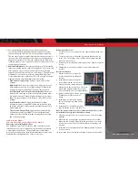
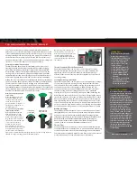
VXL-6s Specifications

Input voltage:


4S/6S LiPo 
(max. 22.2 volts)

Supported Motors: 

Sensorless Brushless

Battery connector: 

Traxxas High-Current 
Connector

Motor connectors: 

TRX 6.5mm bullet 
connectors

Motor/battery wiring: 

10-gauge Maxx® Cable

Weight: 

207g (7.3 oz.)

Case size: 

58mm (2.28”)/ 72mm 
(2.83”)/ 46mm (1.81”)


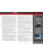
ADJUSTING THE ELECTRONIC SPEED CONTROL

Electronic Speed Control Adjustments

The VXL-6s electronic speed control’s default settings were programmed 
at the factory and should not require adjustment for normal operation. 
The following information is helpful to confirm the settings or allow you to 
customize the settings for your needs.

ATTENTION: USING LiPo BATTERIES

The VXL-6s electronic speed control is designed to operate on 4S or 6S 

LiPo battery power. When you turn your model on, the speed control’s status 
LED is green, indicating that 

Low Voltage Detection

 is activated to prevent 

over-discharging of LiPo batteries. 

LiPo batteries are intended only for the 

most advanced users that are educated on the risks associated with LiPo 
battery use.

DO NOT use Nickel Metal Hydride  
(NiMH) batteries with this model. The 
batteries will become extremely hot  
and damage or injury could occur. 

Verify Low-Voltage Detection setting:

1. Turn on the transmitter (with the throttle at neutral).
2. Connect two fully charged batteries to the VXL-6s.
3. Press and release the EZ-Set button to turn the VXL-6s on. If the LED is solid 

green, then Low-Voltage Detection is ACTIVATED. If the LED is solid red, then 
Low-Voltage Detection is DISABLED (not safe to use LiPo batteries).

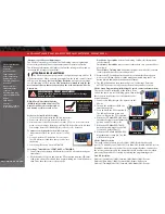
To activate Low-Voltage Detection (LiPo setting):

1.  Make sure the LED on the speed control is on and 

red. 

2.  Press and hold the EZ-Set button for ten seconds. 

The LED will turn off and then light green. Release 
the button.

3.  Low-Voltage Detection is now ACTIVATED.

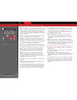
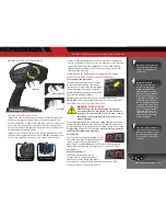
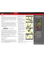
Selecting a Throttle Mode: SPORT, RACE, or TRAINING

1.  Connect two fully charged LiPo batteries to the VXL-6s and turn on your 

transmitter.

2.   With the model off, press and hold the EZ-Set button until the LED turns 

solid green, then solid red and then begins blinking red. It will blink once, 
then twice, then three times, then repeat.


One blink = Sport Mode

 is the default setting. It allows full forward and 

reverse throttle.


Two blinks = Race Mode

 removes reverse throttle in case your track does 

not allow it.


Three blinks = Training Mode

 will slow the model down by 50% to make 

it easier for new drivers to control the model.

3.   Release the EZ-Set button after the number of blinks for the mode you 

wish to select. 

Note

If you missed the mode you wanted, keep the EZ-Set 

button pressed down and the blink cycle will repeat.

4.   The LED will blink and then turn solid green (Low-Voltage Detection 

ACTIVE). The model is ready to drive in the mode you have selected.

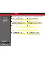
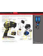
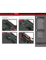
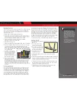
VXL-6s Setup Programming (calibrating the speed control and transmitter)

The speed control is calibrated at the factory. If the 
LED on the speed control is flashing green, then follow 
these steps to recalibrate it (set the throttle to the 
neutral position).
1.   Connect two fully charged LiPo batteries to the 

VXL-6s.

2.   Turn on the transmitter (with the 

throttle at neutral).

3.   Press and hold the EZ-Set button (A).  

The LED will first turn green and 
then red. Release the EZ-Set button.

4.   When the LED blinks RED ONCE, pull 

the throttle trigger to the full throttle 
position and hold it there (B).

5.   When the LED blinks RED TWICE, 

push the throttle trigger to the full 
reverse and hold it there (C).

6.   When the LED blinks GREEN ONCE, 

programming is complete. The LED 
will then shine green.

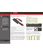
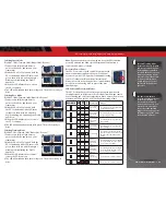
VXL-6s Profile Selection

The speed control is factory set to Profile #1 (100% forward, brakes, and 
reverse). To disable reverse (Profile #2) or to allow 50% forward and 50% reverse 
(Profile #3), follow the steps below. The speed control should be connected to 
the receiver and battery, and the transmitter should be adjusted as described 
previously. The profiles are selected by entering the programming mode.

Profile Description

Profile #1 (Sport Mode): 100% Forward, 100% Brakes, 100% Reverse
Profile #2 (Race Mode): 100% Forward, 100% Brakes, No Reverse
Profile #3 (Training Mode): 50% Forward, 100% Brakes, 50% Reverse

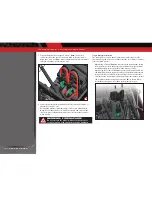
WARNING: FIRE HAZARD!

Do not use LiPo batteries in this vehicle with Low-Voltage 

Detection disabled.

Green then Red

A

Once Red

B

Twice Red

C

Summary of Contents for 85076-4

Page 1: ...MODEL 85076 4 owner s manual...

Page 2: ...t you will find it helpful and fast Be sure and read through the rest of the manual to learn about important safety maintenance and adjustment procedures Turn to page 10 to begin 3 BEFORE YOU PROCEED...

Page 3: ...is also available at Traxxas com support You may also e mail customer support with your question at support Traxxas com Join thousands of registered members in our online community at Traxxas com Tra...

Page 4: ...R TO CHARGE LIPO BATTERIES AS THIS CAN CAUSE FIRE RESULTING IN PROPERTY DAMAGE AND OR PERSONAL INJURY OR DEATH Terms of Use This product is surrendered by Traxxas to the purchaser with the understandi...

Page 5: ...d the maximum manufacturer recommended charge rate DO NOT attempt to charge non rechargeable batteries explosion hazard batteries that have an internal charge circuit or a protection circuit or batter...

Page 6: ...other unauthorized driver Always disconnect the batteries in the model when it is not in use Never store the vehicle with batteries in the model as this can cause a fire leading to property damage ser...

Page 7: ...your hobby dealer to operate and maintain your model Supplied Tools and Equipment Required Equipment Battery and charger style are subject to change and may vary from images 4 AA alkaline batteries Li...

Page 8: ...Electronic Speed Control LED Light Pipe Axle Carrier Receiver Box Antenna Mount Upper Suspension Arm Toe Link Shock Roll Cage Rear Driveshaft Assembly spare Driveshaft Rear Swaybar Linkage Trailing Ar...

Page 9: ...View Motor Spur Gear Pinion Gear Battery Hold Down Steering Servo Chassis Skidplate Rear Upper Link Limit Strap Transmission Front Skidplate Trailing Arm Shock Driveshaft Lower Suspension Arm Rear Axl...

Page 10: ...and that there is no interference from outside sources 3 Install batteries in the transmitter See page 14 8 Detail your model See sidebar page 11 The transmitter requires 4 AA alkaline batteries sold...

Page 11: ...ator and brush arrangement with intelligent electronics that energize the electromagnetic windings in sequence to provide rotation Opposite of a brushed motor the brushless motor has its windings coil...

Page 12: ...of the neutral position of the servos made by adjusting the throttle and steering trim knobs on the face of the transmitter Note The Multi Function knob must be programmed to serve as a throttle trim...

Page 13: ...Trim Multi Function Knob Throttle Trigger Throttle Neutral Adjust Steering Wheel Channel 1 Steering Servo 2200Kv Brushless Motor Channel 2 VXL 6s Electronic Speed Control Antenna Power Switch Battery...

Page 14: ...become extremely hot and damage or injury could occur SELECTING A CHARGER FOR YOUR MODEL Make certain you choose the correct type of charger for the batteries you select Traxxas recommends you choose...

Page 15: ...d menus for the easiest and safest charging solution possible Visit Traxxas com to learn more about this feature and available Traxxas iD chargers and batteries TRAXXAS TQi RADIO VELINEON POWER SYSTEM...

Page 16: ...operation Plug the 4s accessory adapter into the 2s 3s battery connector from the speed control When using a Traxxas 5000mAh 4s battery pack part 2888X install foam battery spacers in the battery com...

Page 17: ...miss it simply turn off the transmitter and start over Always turn on the transmitter before plugging in the battery RADIO SYSTEM BASIC ADJUSTMENTS Throttle Neutral Adjustment The throttle neutral adj...

Page 18: ...ur radio system to ensure that it operates properly 1 Turn on the radio system and check its operation as described in the previous section 2 Have a friend hold the model Make sure hands and clothing...

Page 19: ...ding drifting and so on On surfaces with very little traction loose dirt smooth concrete ice snow increase TSM to maximize acceleration and control Drive with TSM on and off to test how it is making y...

Page 20: ...D turns solid green then solid red and then begins blinking red It will blink once then twice then three times then repeat One blink Sport Mode is the default setting It allows full forward and revers...

Page 21: ...3 When the LED blinks red three times release the EZ Set button 4 The LED will blink and then turn solid green The model is ready to drive Note If you missed the mode you wanted keep the EZ Set butto...

Page 22: ...XL 6s will automatically shut down fail safe mode The LED on the speed control will slowly blink red indicating a low voltage shutdown Stop driving the model The VXL 6s will stay in this mode until fu...

Page 23: ...e obstruction before continuing Do not push or pull objects with the model Because the model is controlled by radio it is subject to radio interference from many sources beyond your control Since radi...

Page 24: ...re Each hole should be near the tire center line 180 degrees apart 3 Confirm that the receiver box O ring and cover are installed correctly and secure Make sure the screws are tight and the blue O rin...

Page 25: ...earings Remove clean and re oil the bearings RECEIVER BOX MAINTAINING A WATERTIGHT SEAL Removing and Installing Radio Gear The unique design of the receiver box allows the removal and installation of...

Page 26: ...gearing from the pin location chart Replace the spur and pinion gears as needed When installing the motor install the pin into its proper location based on the gearing that is chosen The pin on the bo...

Page 27: ...ing Lowering the viscosity of the oil will cause the suspension damping to be reduced Damping should be increased with higher viscosity oil if the model is bottoming easily over jumps Damping should b...

Page 28: ...ve pins are not cracked or extremely worn Additional driveline noise can occur if the driveline components are worn out Remove the gear cover Inspect the spur gear for wear and check the tightness of...

Page 29: ...ight of shock oil available to you From the factory the Desert Racer is equipped with pistons with 1 7mm bypass holes recommended Shock disassembly The shocks must be removed from the vehicle and disa...

Page 30: ...The differential is filled with silicone differential fluid and is sealed to maintain consistent long term performance Changing the oil in the differential with either lower or higher viscosity oil wi...

Page 31: ...ty setting Steering Percentage Dual Rate The Multi Function knob can be set to control the amount percentage of servo travel applied to steering Turning the Multi Function knob fully clockwise will de...

Page 32: ...made with the Multi Function knob are overlaid on top of each other For example if you assign the Multi Function to adjust Steering Percentage and set it for 50 then reassign the knob to control Stee...

Page 33: ...o select any model from a list of model memory entries The transmitter and receiver do it all for you automatically To activate Model Lock 1 Switch on the transmitter and receiver you wish to lock 2 P...

Page 34: ...s how to navigate through the TQi transmitter s various settings and functions Press and hold MENU to enter the Menu Tree and use the following commands to navigate through the menu and select options...

Page 35: ...en LED blinks Press SET red LED blinks x3 Press MENU twice red LED blinks x3 Turn steering wheel to desired max left and right travel x8 Press SET to save each position Turn steering wheel to test set...

Page 36: ...ums minimums or averages Use the recording function to document your dashboard view with sound so that you can keep your eyes on your driving and not miss a single apex Manage up to 30 Models with Tra...

Page 37: ...6250 TRAXXAS WAY McKINNEY TEXAS 75070 1 888 TRAXXAS 180403 85076 4 OM EN R01 owner s manual...

Reviews: