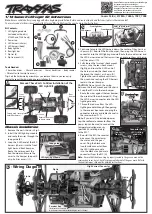
Body installation
1. Use a body reamer or a drill to cut two 7mm
wide holes in the roof of the vehicle body,
as shown (H, I).
Note:
It is important to cut the holes in the
appropriate locations or the LEDs will not mount
correctly (I).
2. Replace the front blank light bar on the top
of the vehicle with the supplied body light
bar.
3. Thread both sections of the LED harness
(body) down through the front drilled
hole. Snap the LED lights into the body
light bar (J).
4. Thread the 2-LED end of the harness up
through the rear drilled hole. Snap the
LED lights into the rear light bar and
position it under the Exo-Cage (K).
5. Pull any excess length of the harness to the
underside of the vehicle body and secure
with the supplied zip ties and mounts.
Position the zip tie mounts as shown (L).
Note:
Use alcohol to clean the underside of the
vehicle body before attaching the zip tie mounts.
6. Plug the wiring harness into the LED
lighting module and reinstall the body (M).
7. The lights will turn on when the ESC is
turned on.
TRAXXAS.com
Traxxas, 6250 Traxxas Way, McKinney, TX 75070, Phone: 972-549-3000, Fax: 972-549-3011, e-mail: [email protected]
HKC20056-R02 201026
11/16” (17mm)
1/4” (6mm)
11/16” (17mm)
1/4” (6mm)
Rear Inside Roof
Front Inside Roof
J
J
Body light
Body light
bar
bar
LED lights
LED lights
LED lights
Rear light bar
TOP VIEW
Exo-cage
H
H
II
KK
LED harness
Zip tie/mount
L
L
LED
Lighting
Module
M
M
Installation of the power tap
Note:
If the wiring from your speed control is not equipped with the 2-pin male connector (black wire
with red connector), you must install the included power tap on the High-Current Connector.
2.6x8mm BCS
ESC Power
Tap Cover
ESC Wiring
*TQi Radio System required for functionality. Visit Traxxas.com for more information.
High-Current
Connector
ESC
Power Tap
ESC Wiring
Temperature/Voltage
Sensor (part #6523,
sold separately)*
Wire colors mismatched
During installation, be sure that
the terminals of the High-Current
Connector and the power tap
make full contact.
ESC Wiring
Power Tap
CAUTION: RISK OF DAMAGE TO
ACCESSORIES!
Note the polarity and wire color on the
pre-installed wires on the power tap. Ensure the polarity is correct during
installation on the High-Current Connector: red (+) (positive), black (-) (negative).


