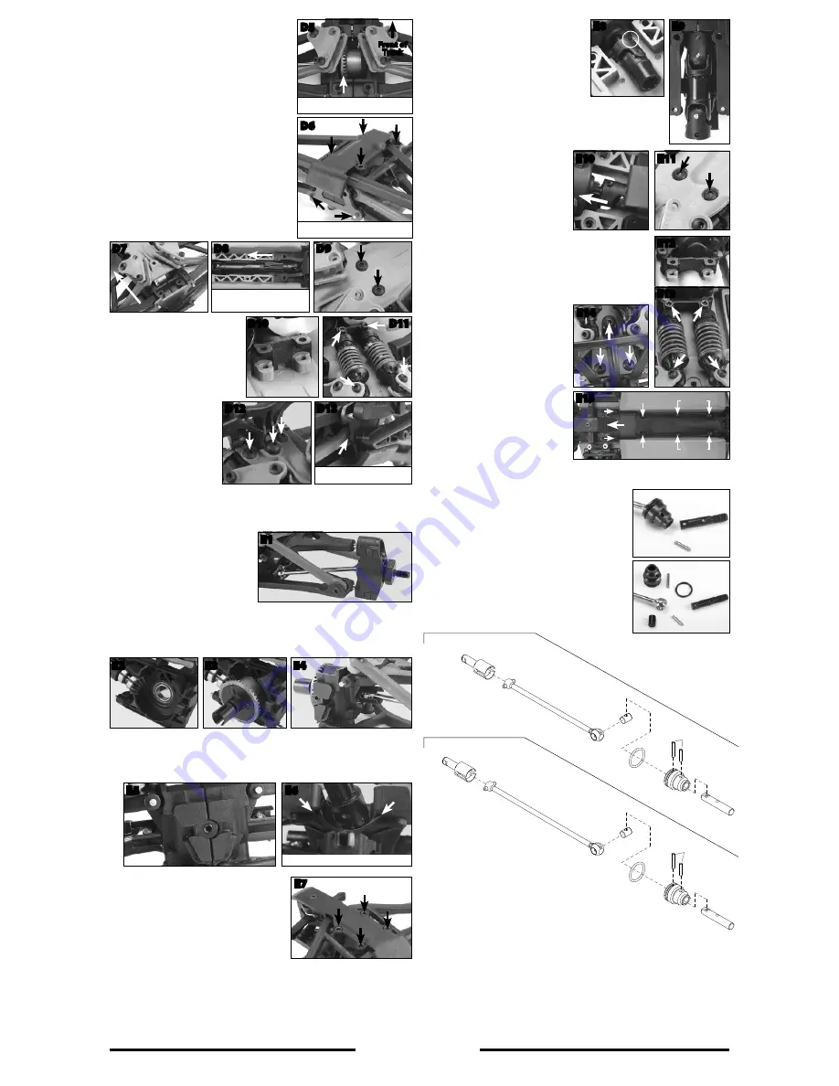
26. Slide the left-side bulkhead half onto the diff
while inserting the left driveshaft into the diff
cup and connect the two bulkhead halves
together (D5).
27. Install the rear bulkhead brace onto the rear
suspension pins and connect it to the rear
bulkhead. Install the rear skid plate onto the
rear end assembly, and secure it with the
four 2.5x8mm cap head screws (D6).
28. Slide the rear end assembly onto the
chassis in the same manner it was removed
(D7). Make sure to connect the two center
driveshaft halves together before securing
the rear end to the chassis (D8). Secure the
rear end to the chassis with the same two
3x10mm button head screws (D9).
Note:
The center skid plate will not be attached to
the chassis until after the front end assembly is
attached to the chassis.
29. Place the rear upper shock
mount onto the chassis (D10).
Secure the shocks to the shock
mount and the rocker arms
with the same 2.5x18mm and
2.5x10mm cap head screws
(D11).
30. Secure the body mount
to the chassis with
the 3x8mm and two
3x10mm button head
screws (D12). Attach the
rear bumper and body
mount assembly to the
chassis. Make sure to
insert the two 2.5x14mm (1/16 Slash) or 2.5x12mm (1/16 E-Revo) cap head
screws through the rear toe link before securing them to the bulkhead (D13).
Front and Final Assembly:
31. Locate the two metal driveshaft
assemblies, and slide the axles
through the inside of each of
the front hub carriers. Make sure
to seat the axles into the ball
bearings. Install the drive pins and
the wheel hexes onto the axles to
keep them in position (E1).
32. Position the front pinion gear assembly into the left-side bulkhead half
(E2). Install the assembled differential into the bulkhead half (E3). Insert the
driveshaft into the diff cup (E4).
33. Slide the right-side bulkhead half onto the diff. Insert the right driveshaft into
the diff cup and connect the two bulkhead halves together (E5).
Note:
When
joining the two front bulkhead halves together, make sure to connect (key in) the
steering bellcrank mount between the two halves (E6).
34. Install the front bulkhead brace onto
the front suspension pins and connect it
to the front bulkhead. Secure the brace
with the 2.5x6mm cap head screw. Next,
install the front skid plate onto the front
end assembly, and secure it with the
four 2.5x8mm cap head screws and the
2.5x12mm countersunk screw (E7).
35. Before joining the front end assembly
to the chassis, remove the front center
driveshaft from the transmission.
Remove the screw pin and pull the
shaft and yoke off of the output shaft
(E8). Join the removed shaft half with
the shaft half connected to the front
differential. Make sure that the drive
shaft halves are keyed in correctly (E9).
36. Slide the front end assembly onto the chassis in the same
manner it was removed. Make sure to reconnect the front
center driveshaft to the front
output shaft of the transmission.
Secure it with the same screw
pin (E10). Next, secure the front
end to the chassis with the same
two 3x10mm button head screws
(E11).
37. Place the front upper shock
mount onto the chassis (E12), and secure the shocks to
the shock mount and the rocker arms with the same
2.5x18mm and 2.5x10mm cap head screws (E13).
38. Attach the front bumper and body mount assembly to
the chassis. Secure the body mount to the chassis with
the 3x6mm and two 3x10mm
button head screws (E14).
39. Attach the center skid plate onto
the chassis and secure it with
the same screws: (4) 3x8mm, (2)
3x10mm, and (2) 3x15mm button
head screws.
Note:
The front edge
of the center skid plate must slide
underneath the front skid plate
(E15).
Tip:
Loosen (or remove) the
steering bellcrank screw to allow
the front skid plate to flex for
easier installation.
40. Finally, install the wheels onto the
axles.
Appendix:
Metal driveshaft disassembly:
• Remove the drive pin from the drive cup; then,
pull the axle from the cup.
• Remove the O-ring from the drive cup to access
the large drive pin. Press the large drive pin out of
the drive cup; then, pull the driveshaft out of the
drive cup. The round cross pin should fall out of
the driveshaft.
TRAXXAS.com
Traxxas, 6250 Traxxas Way, McKinney, TX 75070, Phone: 972-549-3000, Fax: 972-549-3011, e-mail: [email protected]
D5
Front of
Truck
D6
D7
D8
D9
D10
D11
D13
E1
E2
E3
E4
E5
E6
E7
E8
E9
D12
E10
E12
E13
E14
E15
E11
Slide under skid plate
3x8mm
3x10mm
3x10mm
3x15mm
3x15mm
3x8mm
Note the ring gear is on the left side when
looking at the rear of the chassis.
Slide the brace over the suspension pins
before installing the rear skid plate.
Connect the center shaft halves
together before securing the rear
assembly to the chassis.
Insert the screws through the toe link
ends before tightening them.
Key the bellcrank mount into the bulkhead halves.
If you have questions or need technical assistance, call Traxxas at
1-888-TRAXXAS
(1-888-872-9927) (U.S. residents only)
7052
7052
7151X
7053
7055
7055
7055
7055
7055
7055
7055
7055
7055
7153
7051X
7055
Replacement Parts
7052 Drive cups, inner (2) 1/16th E-Revo/Slash
(steel constant-velocity driveshafts)
7053 Driveshaft, steel constant-velocity, 1/16th Slash (shaft only,
48mm)/ drive cup pin (1)
7055 Rebuild kit (for 1/16th E-Revo/Slash steel constant-velocity driveshafts)
(includes pins, O-rings, stub axles for driveshafts assemblies)
7153 Driveshaft, steel constant-velocity, 1/16th E-Revo (shaft only, 68mm)/
drive cup pin (1)
Driveshaft Assemblies


