background image

STAMPEDE 4x4 VXL 

  15

6, 7

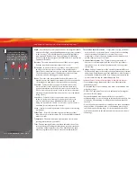
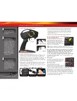
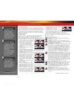
Using Reverse: While driving, 
push the throttle trigger 
forward to apply brakes. 
Once stopped, return the 
throttle trigger to neutral. 
Push the throttle trigger 
forward again to engage 
proportional reverse. 

TRAXXAS TQ

i

 RADIO & VELINEON POWER SYSTEM

USING THE RADIO SYSTEM

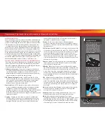
The TQi Radio System has been pre-adjusted at the factory. The 
adjustment should be checked before running the model in case of 
movement during shipping. Here’s how:

1.  Turn the transmitter switch on. The status LED on the transmitter 

should be solid green (not flashing).

2. 

Elevate the model on a block or a stand so that all the tires are 
off the ground.

 Make sure your hands are clear of the moving 

parts of the model.

3.  Plug the battery pack in the model into the speed control. 

4.


The on/off switch is integrated into the speed control. With the 
transmitter on, press and release the EZ-Set button (.25 seconds). 
The LED will shine RED (see note below).  This turns the model 
on. To turn the VXL-3s off, press and hold the EZ-Set button 
until the LED turns off (.5 seconds).  

Note: 

If the LED shines 

green, Low-Voltage Detection is activated. This will cause erratic 
performance from the included NiMH battery pack. The default 
factory setting is for Low-Voltage Detection to be disabled 
(LED shines red). Make sure to turn the low voltage detection 
on when using LiPo batteries. 

Never use LiPo batteries while 

Low-Voltage Detection is turned off. 

See page 17 for more 

information.

5.  Turn the steering wheel on the transmitter back and forth and 

check for rapid operation of the steering servo. Also, check that 
the steering mechanism is not loose or binding. If the steering 
operates slowly, check for weak batteries.

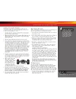
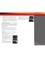
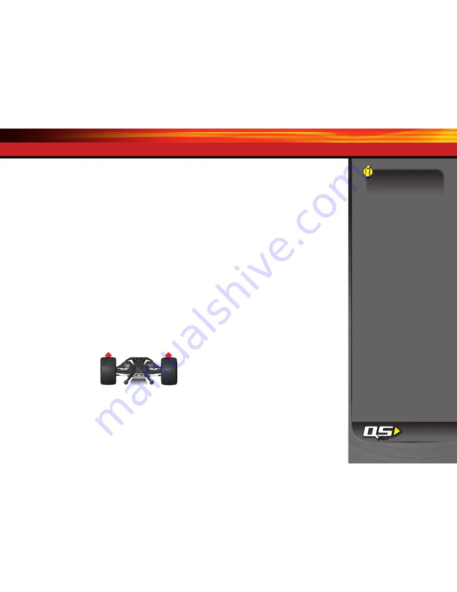
6.  When looking down at the 

model, the front wheels 
should be pointing straight 
ahead. If the wheels are 
turned slightly to the left 
or right, slowly adjust the 
steering trim control on the 
transmitter until they are pointing straight ahead. 

7.  Gently operate the throttle trigger to ensure that you have 

forward and reverse operation, and that the motor stops when 
the throttle trigger is at neutral. 

Warning

Do not apply full 

throttle in forward or reverse while the model is elevated.

8.  Once adjustments are made, turn off the receiver on your model, 

followed by the hand-held transmitter.

Range-Testing the Radio System

Before each running session with your model, you should range-test 
your radio system to ensure that it operates properly.

1.   Turn on the radio system and check its operation as described in 

the previous section.

2.   Have a friend hold the model. Make sure hands and clothing are 

clear of the wheels and other moving parts on the model.

3.   Make sure your transmitter antenna is fully extended, and then 

walk away from the model with the transmitter until you reach 
the farthest distance you plan to operate the model.

4.   Operate the controls on the transmitter once again to be sure 

that the model responds correctly. 

5.


  Do not attempt to operate the model if there is any problem 

with the radio system or any external interference with your 
radio signal at your location. 


• Higher Speeds Require Greater Distance


The faster you  drive your model, the more quickly it will near the 
limit of radio range. At 60mph, a model can cover 88 feet every 
second! It’s a thrill, but use caution to keep your model in range. 
If you want to see your model achieve its maximum speed, it 
is best to position yourself in the middle of the truck’s running 
area, not the far end, so you drive the truck towards and past 
your position. In addition to maximizing the radio’s range, this 
technique will keep your model closer to you, making it easier to 
see and control. 


No matter how fast or far you drive your model, always leave 
adequate space between you, the model, and others. Never drive 
directly toward yourself or others. 

TQi Binding Instructions

For proper operation, the transmitter and receiver must be
electronically ‘bound.’ 

This has been done for you at the factory.

Should you ever need to re-bind the system or bind to another 
transmitter or receiver, follow these instructions. 

Note

: the receiver 

must be connected to a 4.8-6.0v (nominal) power source for binding, 
and the transmitter and receiver must be within 5 feet of each other.

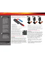
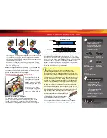
1.   Press and hold the transmitter’s SET button as you switch the 

transmitter on. The transmitter’s LED will flash red slowly.  
Release the SET button.

Summary of Contents for 6708L Stampede 4X4 VXL

Page 1: ...л чит т нич ю н льт цию гл т чн Б з вы дны www sotmarket ru д бн я инф м ция т в тзывы бз ы и ы Инструкция для VXL 1 10 4WD TRA6708L Traxxas Stampede Перейти в карточку товара 8 800 775 98 98 ...

Page 2: ...owner s manual MODEL 6708L MODEL 6708 ...

Page 3: ...t how to contact us and what your support options are Quick Start This manual is designed with a Quick Start path that outlines the necessary procedures to get your model up and running in the shortest time possible If you are an experienced R C enthusiast you will ind it helpful and fast Be sure and read through the rest of the manual to learn about important safety maintenance and adjustment pro...

Page 4: ...f your product support needs We want you to be thoroughly satisied with your new model SAFETY PRECAUTIONS All of us at Traxxas want you to safely enjoy your new model Operate your model sensibly and with care and it will be exciting safe and fun for you and those around you Failure to operate your model in a safe and responsible manner may result in property damage and serious injury The precautio...

Page 5: ... battery use It is critical for you the user to follow all other instructions supplied by the battery manufacturer and the charger manufacturer for proper charging use and storage of LiPo batteries Make sure you understand how to use your LiPo batteries Be aware that Traxxas shall not be liable for any special indirect incidental or consequential damages arising out of the installation and or use ...

Page 6: ...er nearby in case of ire BEFORE you charge ALWAYS conirm that the charger settings exactly match the type chemistry speciication and coniguration of the battery to be charged DO NOT use the 2 3 cell LiPo charger 2935 to charge NiMH batteries DO NOT exceed the battery manufacturer s maximum recommended charge rate DO NOT disassemble crush short circuit or expose the batteries or cells to lame or an...

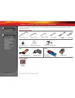
Page 7: ...ENT Your model comes with a set of specialty metric tools You ll need to purchase other items available from your hobby dealer to operate and maintain your model Preload spacers and shock pistons 4 AA alkaline batteries Body clips and body washers Optional pinion gear 2 0mm L wrench 1 5mm L wrench 4 way wrench U joint wrench Supplied Tools and Equipment Required Equipment Battery charger LiPo batt...

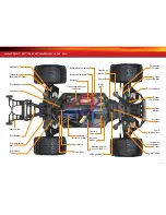
Page 8: ...ht Pipe Battery Hold Down Battery Receiver Box Antenna Mount Front Suspension Arm Front Bumper Steering Servo Shock Oil Damper Turnbuckle Toe Link Turnbuckle Front Camber Link Turnbuckle Rear Camber Link Rear Shock Tower Traxxas High Current Connector Rear Body Mount Chassis Front Body Mount Front Shock Tower Drive Shaft Half Shaft Rear Suspension Arm Half Shaft Shock Guard ...

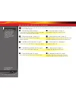
Page 9: ...ference from outside sources 3 Install batteries in the transmitter See page 12 8 Detail your model See sidebar page 9 The transmitter requires 4 AA alkaline or rechargeable batteries Apply other decals if desired 4 Install the battery pack in the model See page 13 9 Drive your model See page 19 Your model requires a fully charged battery pack Driving tips and adjustments for your model 5 Turn on ...

Page 10: ...y eliminate cogging Current Current is a measure of power low through the electronics usually measured in amps If you think of a wire as a garden hose current is a measure of how much water is lowing through the hose ESC Electronic Speed Control An electronic speed control is the electronic motor control inside the model The VXL 3s electronic speed control uses advanced circuitry to provide precis...

Page 11: ...d radio unit that sends throttle and steering instructions to your model Trim The ine tuning adjustment of the neutral position of the servos made by adjusting the throttle and steering trim knobs on the face of the transmitter Note The Multi Function knob must be programmed to serve as a throttle trim adjustment Thermal Shutdown Protection Temperature sensing electronics used in the VXL 3s electr...

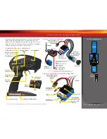
Page 12: ...th one servo and an electronic speed control MODEL WIRING DIAGRAM Antenna Receiver Velineon Brushless Motor see sidebar for proper motor wiring Channel 2 Electronic Speed Control Channel 1 Steering Servo to Motor LED EZ Set Button On Off Button Heat Sink VXL 3s ELECTRONIC SPEED CONTROL Traxxas High Current Connector Male to Battery Motor Cap Traxxas High Current Connector Male to Battery Auxiliary...

Page 13: ...sconnect the battery from the charger after charging CHARGING THE LiPo BATTERY PACK Model 6708L Before charging the provided 2 Cell LiPo battery please read and understand all safety precautions at the beginning of this manual The included charger can be used to charge the provided battery pack The supplied charger has an output rate of 800mAh 0 8 amps and may require up to seven hours to fully ch...

Page 14: ...ded foam block in the front of the battery compartment 25mm side Standard NiMH stick pack setup 23mm side Side by side NiMH pack setup Using Other Batteries Your model is equipped with a state of the art high performance power system It is designed to be able to low large amounts of power with the least amount of restriction The beneits are drastically increased speed and acceleration However this...

Page 15: ...dicating a failure to link If you miss it simply turn off the transmitter and start over Always turn on the transmitter before plugging in the battery RADIO SYSTEM BASIC ADJUSTMENTS Throttle Neutral Adjustment The throttle neutral adjustment is located on the transmitter face and controls the forward reverse travel of the throttle trigger Change the adjustment by pressing the button and sliding it...

Page 16: ...neutral Warning Do not apply full throttle in forward or reverse while the model is elevated 8 Once adjustments are made turn off the receiver on your model followed by the hand held transmitter Range Testing the Radio System Before each running session with your model you should range test your radio system to ensure that it operates properly 1 Turn on the radio system and check its operation as ...

Page 17: ...Steering Sensitivity Negative Exponential By turning the Multi Function knob clockwise the steering sensitivity of the model will be decreased Note that a relatively large amount of steering wheel travel results in a smaller amount of servo travel The farther you turn the knob the more pronounced the effect becomes Decreased steering sensitivity may be helpful when driving on low traction surfaces...

Page 18: ...r is properly adjusted set back to the factory defaults Otherwise you may not get the best performance from your speed control The transmitter should be adjusted as follows If the transmitter settings have been adjusted reset them to the factory defaults 1 Turn the transmitter off 2 Hold both MENU and SET 3 Turn the transmitter on 4 Release MENU and SET The transmitter LED will blink red 5 Press S...

Page 19: ...w Voltage Detection ACTIVE or red Low Voltage Detection DISABLED The model is ready to drive Selecting Training Mode Proile 3 50 Forward 100 Brakes 50 Reverse 1 Connect a fully charged battery pack to the VXL 3s and turn on your transmitter 2 With the VXL 3s off press and hold the EZ Set button until the LED turns solid green then solid red and then begins blinking red indicating the Proile number...

Page 20: ...ry pack will theoretically run twice as long as a 1500mAh sport pack Because of the wide variation in the types of batteries that are available and the methods with which they can be charged it s impossible to give exact run times for the model Another major factor that affects run time is how the model is driven Run times may decrease when the model is driven repetitively from a stop to top speed...

Page 21: ...oled by water contact and will not give an accurate indication of appropriate gearing Use special care when operating your model in muddy conditions Stop operating your model if it appears to be straining due to the tackiness of the mud or build up of mud on the chassis Do not allow mud to collect on the motor or pack around the motor After Running Your Vehicle in Wet Conditions 1 Drain the tires ...

Page 22: ...by removing the two 3x10mm cap screws 3 To remove the receiver from the box simply lift it out and set to the side The antenna wire is still inside the clamp area and cannot be removed yet 4 Unplug the servo cables from the receiver and remove the receiver Receiver Installation 1 Install the electronic speed control ESC servo and antenna wiring through the receiver box top A 2 Plug ESC and servo w...

Page 23: ... to 1 to 2 of negative camber In the rear adjust the wheels to 1 to 2 of negative camber These adjustments should be set with the truck positioned at its normal ride height Shock Mounting Positions Big bumps and rough terrain require a softer suspension with the maximum possible suspension travel and ride height Racing on a prepared track or on road use requires a lower ride height and irmer more ...

Page 24: ...ed toward the receiver s LED 3 Turn the transmitter power switch on Make certain the transmitter s batteries are not depleted 4 Turn the transmitter s steering trim knob to the center 0 position 5 Disconnect motor wires A and C see page 11 to prevent the motor from turning during the next steps Connect a fresh battery pack to the speed control and turn on the ESC see page 17 The servo s output sha...

Page 25: ...ne Inspect the driveline for signs of wear such as worn drive yokes dirty axle half shafts and any unusual noise or binding If a U joint pops apart then it is time to replace the part Remove the gear cover Inspect the spur gear for wear and check the tightness of the set screws in the pinion gears Tighten clean or replace components as needed Storage When you are through running the model for the ...

Page 26: ...nter further move the outer camber link ends to the lower position on the C hub Bump steer correction Bump steer refers to unwanted steering inputs caused by suspension movement Your model s suspension geometry is designed to minimize bump steer If you are using the upper hole on the C hub image A and either of the two lower holes on the shock tower positions 3 or 4 in Front image the tie rod ball...

Page 27: ...the wiring diagram on page 11 Sensored Brushless Motors The VXL 3s is fully compatible with sensored brushless motors Sensor motors use an additional sensor installed in the motor to communicate rotor position to the speed control The VXL 3s features a covered auxiliary port that accepts aftermarket motor sensors on the front face of the unit The VXL 3s has built in Sensor Motor Backup Protection ...

Page 28: ...in consistent long term performance Changing the oil in the differential with either lower or higher viscosity oil will vary the performance characteristics of the differentials Changing to a higher viscosity oil in the differential will reduce the tendency for motor power to be transferred to the wheel with the least traction You may notice this when making sharp turns on slick surfaces The unloa...

Page 29: ...differential cover Do not remove the two screws that secure the shock tower 7 Remove the differential cover and slide the differential out of the front of the case 8 To reinstall the differential reverse the steps Refilling the differential 1 Remove the four 2 5x10mm screws from the differential case and carefully pull the diff case halves apart Work over a towel to collect any luid that drips fro...

Page 30: ...ment settings you select will represent what you wish to be the servo s maximum travel the Steering Percentage or Braking Percentage functions will not override the End Point settings Steering and Throttle Sub Trim The Sub Trim function is used to precisely set the neutral point of the steering or throttle servo in the event that simply setting the trim knob to zero does not completely center the ...

Page 31: ... blink green four times repeatedly 4 Press SET once The status LED will blink green once repeatedly 5 Press MENU once The status LED will blink green twice repeatedly 6 Press SET The memory is now selected to be deleted Press SET to delete the model Press and hold MENU to return to driving mode Failsafe Your Traxxas radio system is equipped with a built in failsafe function that returns the thrott...

Page 32: ...ave Push forward to desired end point and press set to save To reset max throw Let go of controls and press SET The Menu Tree below shows how to navigate through the TQi transmitter s various settings and functions Press and hold MENU to enter the Menu Tree and use the following commands to navigate through the menu and select options MENU When you enter a menu you always start at the top Press ME...

Page 33: ... LED blinks Press SET red LED blinks x3 Press MENU twice red LED blinks x3 Turn steering wheel to desired max left and right travel x8 Press SET to save each position Turn steering wheel to test settings IF END POINTS ARE OK Press hold MENU returns to driving mode IF END POINTS NEED TO BE CHANGED Press SET and repeat steps 6 8 To reset the END POINTS of STEERING servo to defaults Press hold MENU g...

Page 34: ...options Control Drive Effects settings such as steering and throttle sensitivity steering percentage braking strength and throttle trim by simply touching and dragging the sliders on the screen Real Time Telemetry When you equip your model with sensors the Traxxas Link dashboard comes to life showing you speed battery voltage rpm and temperature Set threshold warnings and log maximums minimums or ...

Page 35: ...1 100 Klein Road Plano Texas 75074 1 888 TRAXXAS 121112 6708OM LN EN R00 owner s manual ...

Page 36: ...л т з з любым д бным б м гл т чн я л жб дд ж и Д т в з з в в ии ф мл ни дит нл н з 2 мин ты м нии Д т в и л т вин и тзывы ции и ид и VXL 1 10 4WD TRA6708L Traxxas Stampede Описание Характеристики ...

Reviews: