


20 • 1/16 SUMMIT
Positive camber
Negative camber
TUNING ADJUSTMENTS
A camber gauge (available
at your local hobby shop)
can be a useful tool for
alignment setting.
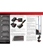
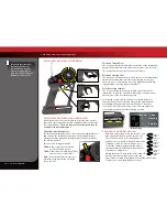
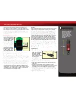
To achieve a good starting
point for the slipper clutch,
tighten the slipper clutch
adjusting nut clockwise until
the slipper clutch adjusting
spring fully collapses (do not
over tighten), and then turn
the slipper clutch nut counter-
clockwise
¾
to 1 turn.
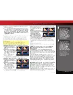
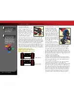
Static Camber Adjustment
The wheels can be set to have either
positive or negative camber (see
illustration below). The camber angle
changes as the wheel moves up and
down through its range of travel. Static
camber is the camber angle at the
wheel when the vehicle is set at its
normal, stationary ride height.
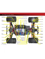
The suspension pivot balls located in the axle carriers adjust the
static camber. Camber is factory-set at negative 1-degree, with
the pivot balls threaded all the way into the suspension arms. To
adjust static camber, insert the supplied 2mm hex wrench into the
pivot ball (compressing the suspension until the arms are parallel
to the ground will allow for easier hex wrench engagement).
Negative camber can be increased by unthreading the lower pivot
ball. Zero camber or positive camber (not recommended) can be
achieved by unthreading the upper pivot ball. Note that camber
changes will also effect the toe angle of the wheel being adjusted.
Static Camber Base Factory Settings
Front:
1-degree negative camber each side
Rear:
1-degree negative camber each side
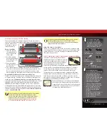
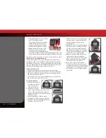
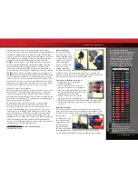
TRANSMISSION TUNING
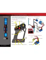
Adjusting the Slipper Clutch
Your model is equipped with an
adjustable Torque Control slipper
clutch which is built into the large
spur gear. The purpose of the slipper
clutch is to prevent over-stressing
of the drivetrain and transmission
gears. It may also be used to regulate
the amount of power sent to the rear
wheels to prevent tire spin. When it
slips, the slipper clutch makes a high-
pitch, whining noise.
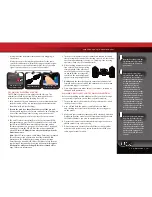
To adjust the slipper clutch, first
remove the receiver box cover. Next,
remove the single large hex screw
from the motor plate using the supplied 2.5mm wrench. Then
rotate the motor and mount to the side of the model. The slipper
clutch is integrated into the main spur gear on the transmission.
The slipper clutch is adjusted using the spring-loaded locknut on
the slipper shaft. Use the supplied universal wrench. To tighten or
loosen the slipper nut, insert the 1.5mm hex wrench into the hole in
the end of the slipper shaft. This locks the shaft for adjustments. Turn
the adjustment nut clockwise to tighten (less slippage) and counter-
clockwise to loosen (more slippage).
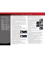
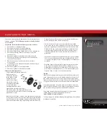
Tuning the Sealed Gear Differentials
Your model’s front and rear gear differentials allow the left and
right wheels to spin at different speeds while turning so that the
tires do not scuff or skid. This decreases the turning radius and
increases steering performance.
The performance of the differentials can be tuned for different
driving conditions and performance requirements. The
differentials are filled with silicone differential fluid, and are sealed
to maintain consistent long-term performance. Changing the oil
in the differential with either lower or higher viscosity oil will vary
the performance characteristics of the differentials. Changing to
a higher viscosity oil in the differential will reduce the tendency
for power to be transferred to the wheel with the least traction.
You may notice this when making sharp turns on slick surfaces.
The unloaded wheels on the inside of the turn have the least


